Magnetic field fluctuation for beam smoothing

a beam profile and magnetic field technology, applied in static indicating devices, instruments, vacuum evaporation coatings, etc., can solve the problems of overall productivity decline, and the inability to achieve the desired gaussian curve beam profile,

Active Publication Date: 2014-07-31
ADVANCED ION BEAM TECHNOLOGY INC
View PDF4 Cites 9 Cited by
  • Summary
  • Abstract
  • Description
  • Claims
  • Application Information

AI Technical Summary

Benefits of technology

[0007]In one exemplary embodiment, a method for implanting ions in a work piece may use an ion implantation tool having an ion beam source, a mass analyzing magnet, a plurality of separately driven electromagnets, and one or more separately driven auxiliary electromagnets. The method may include generating a beam of ions with the ion beam source. The method may further include driving the plurality of separately driven electromagnets to generate a magnetic field to shape an ion beam profile of the ion beam and driving the one or more separately driven auxiliary electromagnets with a periodic signal to generate a fluctuating magnetic field. The fluctuating magnetic field may cause the ion beam profile shape to change continuously to smooth a time-averaged ion beam profile of the ion beam. The method may also include guiding the ion beam along an ion beam path toward a work piece using the mass analyzing magnet to implant ions on the work piece.
[0008]The method may further include driving a set of m...

Problems solved by technology

However, in the example of a spot beam, the desired Gaussian curve-shaped beam profile may not always be readily achievable due to the limitations of beam tuning, and specifically the difficulties of removing noise, spikes, peaks, shoulders, and the like from a beam profi...

Method used


Image

  • Magnetic field fluctuation for beam smoothing
  • Magnetic field fluctuation for beam smoothing
  • Magnetic field fluctuation for beam smoothing

Examples


Embodiment Construction

[0019]The following description is presented to enable a person of ordinary skill in the art to make and use the various embodiments. Descriptions of specific systems, devices, methods, and applications are provided only as examples. Various modifications to the examples described herein will be readily apparent to those of ordinary skill in the art, and the general principles defined herein may be applied to other examples and applications without departing from the spirit and scope of the various embodiments. Thus, the various embodiments are not intended to be limited to the examples described herein and shown, but are to be accorded the scope consistent with the claims.

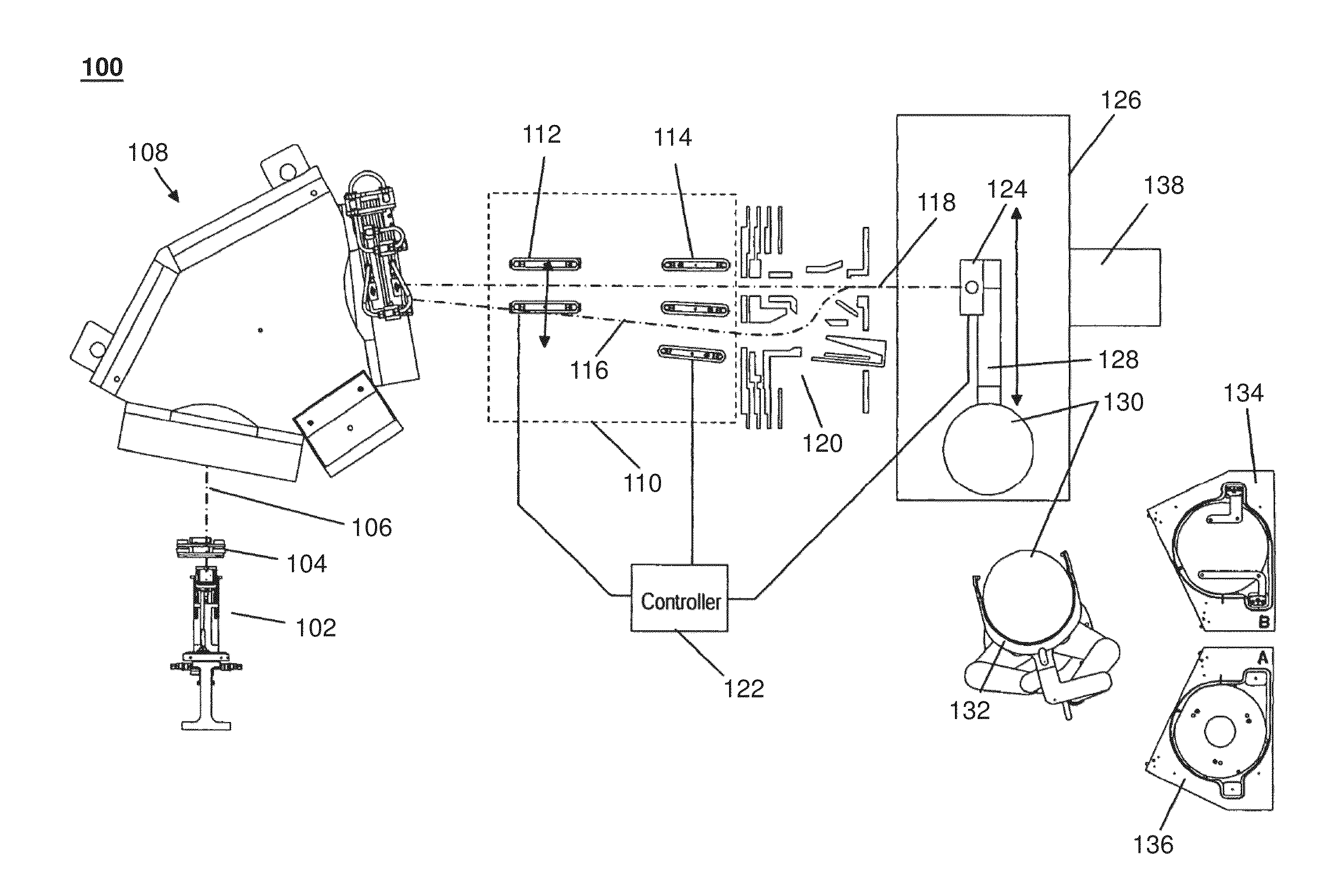
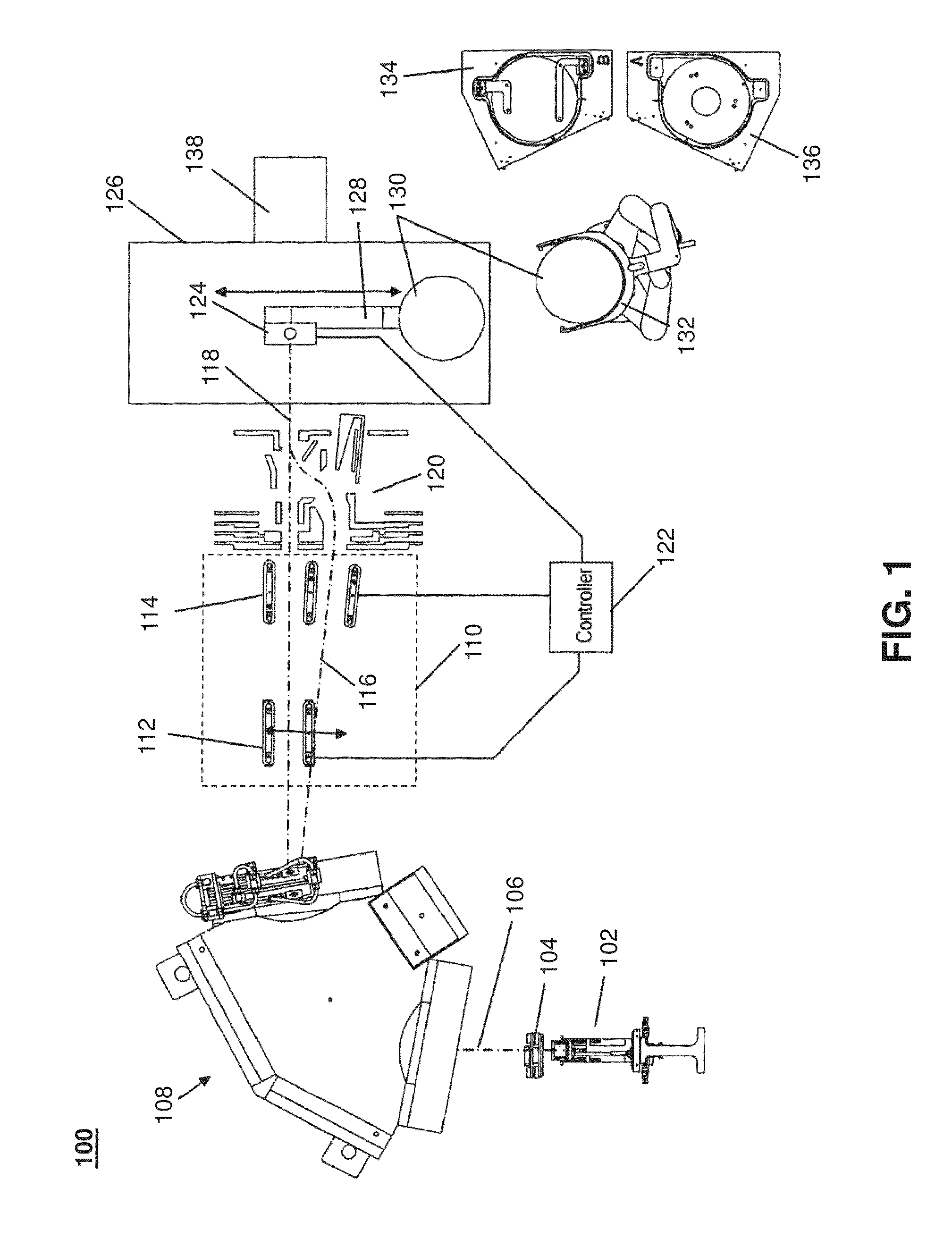
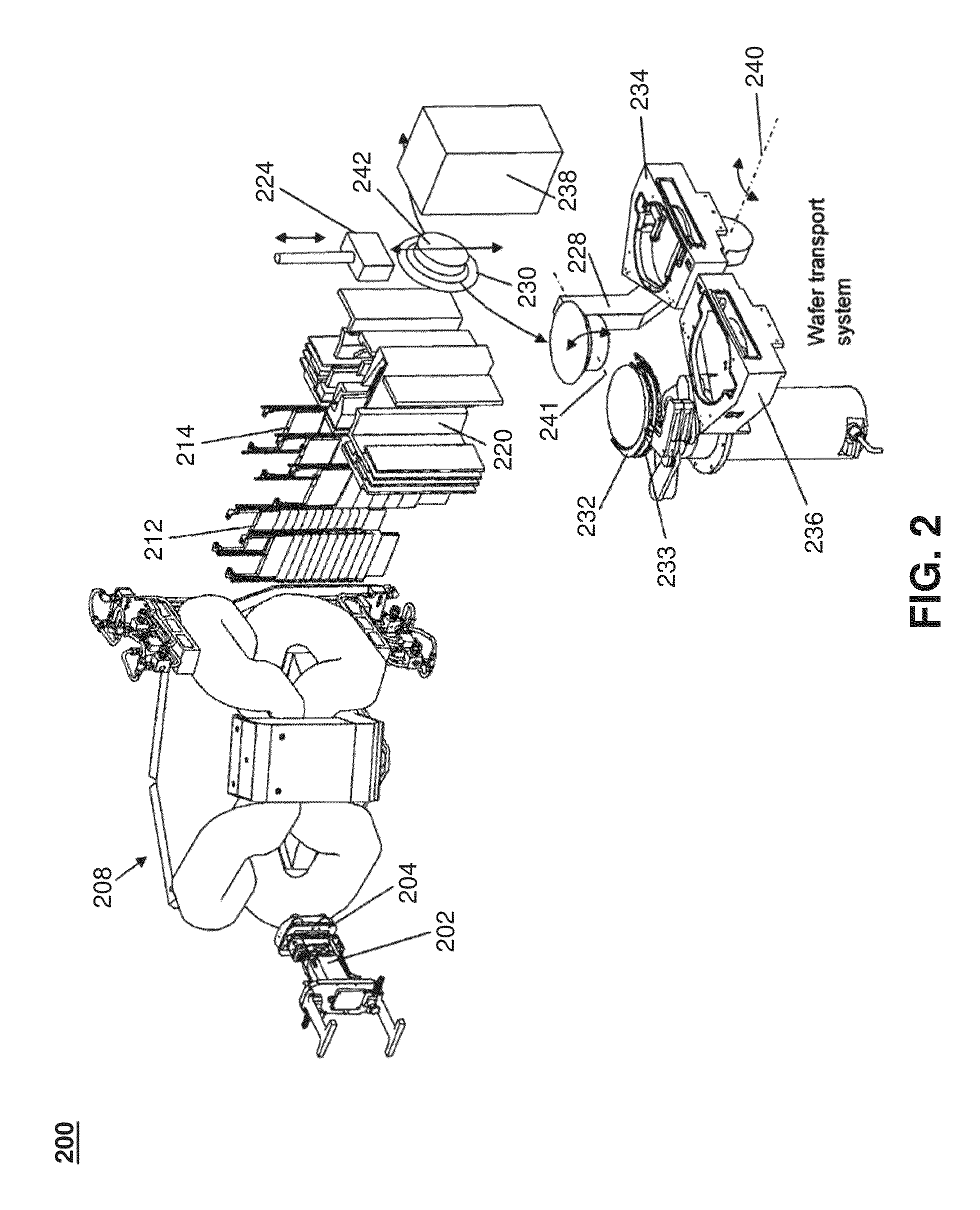
[0020]Ion implantation may be used to introduce ions into a work piece, such as a silicon wafer, in fabricating integrated semiconductor devices. As integrated circuits shrink in size while also improving in speed and functionality, the tolerances for doping variations in silicon wafers are decreasing. Likewise, a...


PUM

PropertyMeasurementUnit
Concentrationaaaaaaaaaa
Magnetic fieldaaaaaaaaaa
Widthaaaaaaaaaa

Abstract

The time-averaged ion beam profile of an ion beam for implanting ions on a work piece may be smoothed to reduce noise, spikes, peaks, and the like and to improve dosage uniformity. Auxiliary magnetic field devices, such as electromagnets, may be located along an ion beam path and may be driven by periodic signals to generate a fluctuating magnetic field to smooth the ion beam profile (i.e., beam current density profile). The auxiliary magnetic field devices may be positioned outside the width and height of the ion beam, and may generate a non-uniform fluctuating magnetic field that may be strongest near the center of the ion beam where the highest concentration of ions may be positioned. The fluctuating magnetic field may cause the beam profile shape to change continuously, thereby averaging out noise over time.

Description

CROSS-REFERENCE TO RELATED APPLICATIONS[0001]This application claims priority to U.S. Provisional Application No. 61 / 757,068 filed with the U.S. Patent and Trademark Office on Jan. 25, 2013, the entire contents of which are hereby incorporated by reference.BACKGROUND[0002]1. Field[0003]The present disclosure relates generally to dopant implantation of a work piece and, more specifically, to smoothing a time-averaged ion implantation beam profile by subjecting the beam to a fluctuating magnetic field.[0004]2. Related Art[0005]Dopant implantation, such as ion implantation, is a process used in fabricating integrated semiconductor devices whereby conductivity-altering impurities, such as ions, are introduced into a work piece, such as a silicon wafer, a semiconductor plate, a glass plate, or the like. An ion implanter or ion implantation tool may include an ion source to generate the impurity material and a mass analyzer to form an ion implant beam with ions of a specific mass-to-charg...

Claims


Application Information

Patent Timeline
IPC IPC(8): H01J29/46C23C14/48
CPCH01J29/46C23C14/48H01J37/1475H01J37/3171H01J2237/152H01J2237/1526H01J2237/303H01J2237/31701H01J2237/31703
Inventor BAI, XIAOWAN, ZHIMINBERRIAN, DONALD WAYNE
Owner ADVANCED ION BEAM TECHNOLOGY INC
Why Eureka
Try Eureka