
Linear plasma source

a plasma source and linear technology, applied in the field of solar cell production, can solve the problems of high production cost, complex process, and inability to ensure plasma uniformity, and achieve the effects of high production speed, low production cost and simple structur

Active Publication Date: 2014-08-07
SHENZHEN JT AUTOMATION EQUIP CO LTD
View PDF29 Cites 4 Cited by
  • Summary
  • Abstract
  • Description
  • Claims
  • Application Information

AI Technical Summary

Benefits of technology

The present application provides a linear plasma source with the following technical effects: simple structure, low production cost, good uniformity and high film compactness. The plasma is generated by processing the reaction gas released by the internal pipeline using electrode plates. The electromagnetic coil generates an effective magnetic field that restricts the direction of movement of the plasma and increases its density. This results in a more uniform plasma release and a higher film deposition or etching speed. The film formed is also more uniform and compact.

Problems solved by technology

However, the linear plasma source in the prior art has disadvantages that the production cost is high, the process is complicated and the uniformity of the plasma can not be ensured.

Method used


Image

  • Linear plasma source
  • Linear plasma source
  • Linear plasma source

Examples


Embodiment Construction

[0017]The technical solutions in the embodiments of the present application will be described clearly and completely hereinafter in conjunction with the drawings in the embodiments of the present application. Apparently, the described embodiments are only a part of the embodiments of the present application, rather than all embodiments. Based on the embodiments in the present application, all of other embodiments, made by the person skilled in the art without any creative efforts, fall into the protection scope of the present application.

[0018]The embodiments of the present application provide a linear plasma source which will be described in detail below.

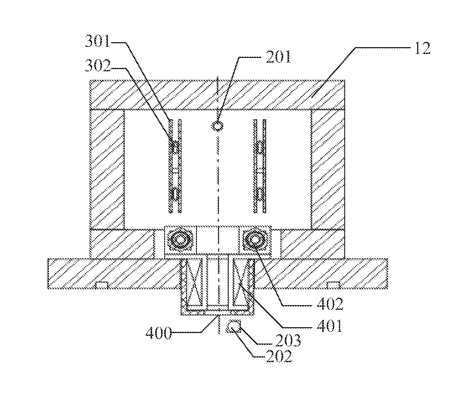
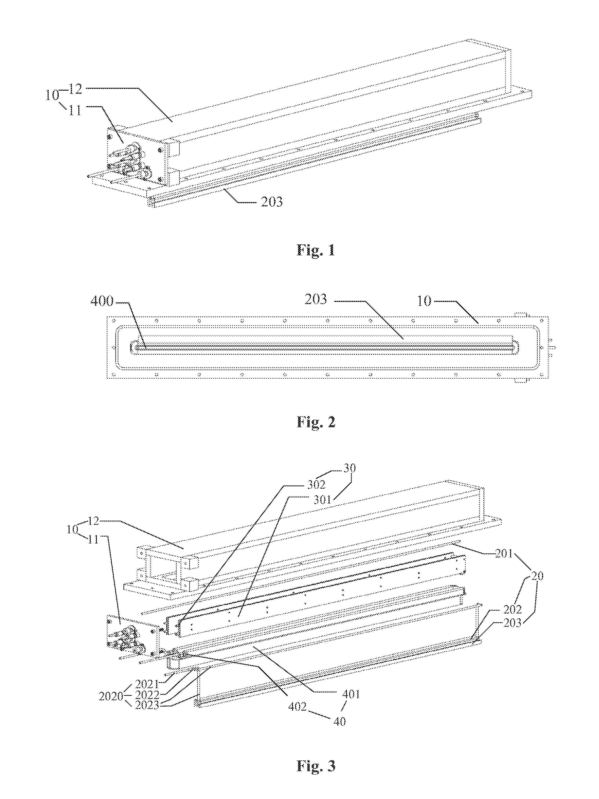
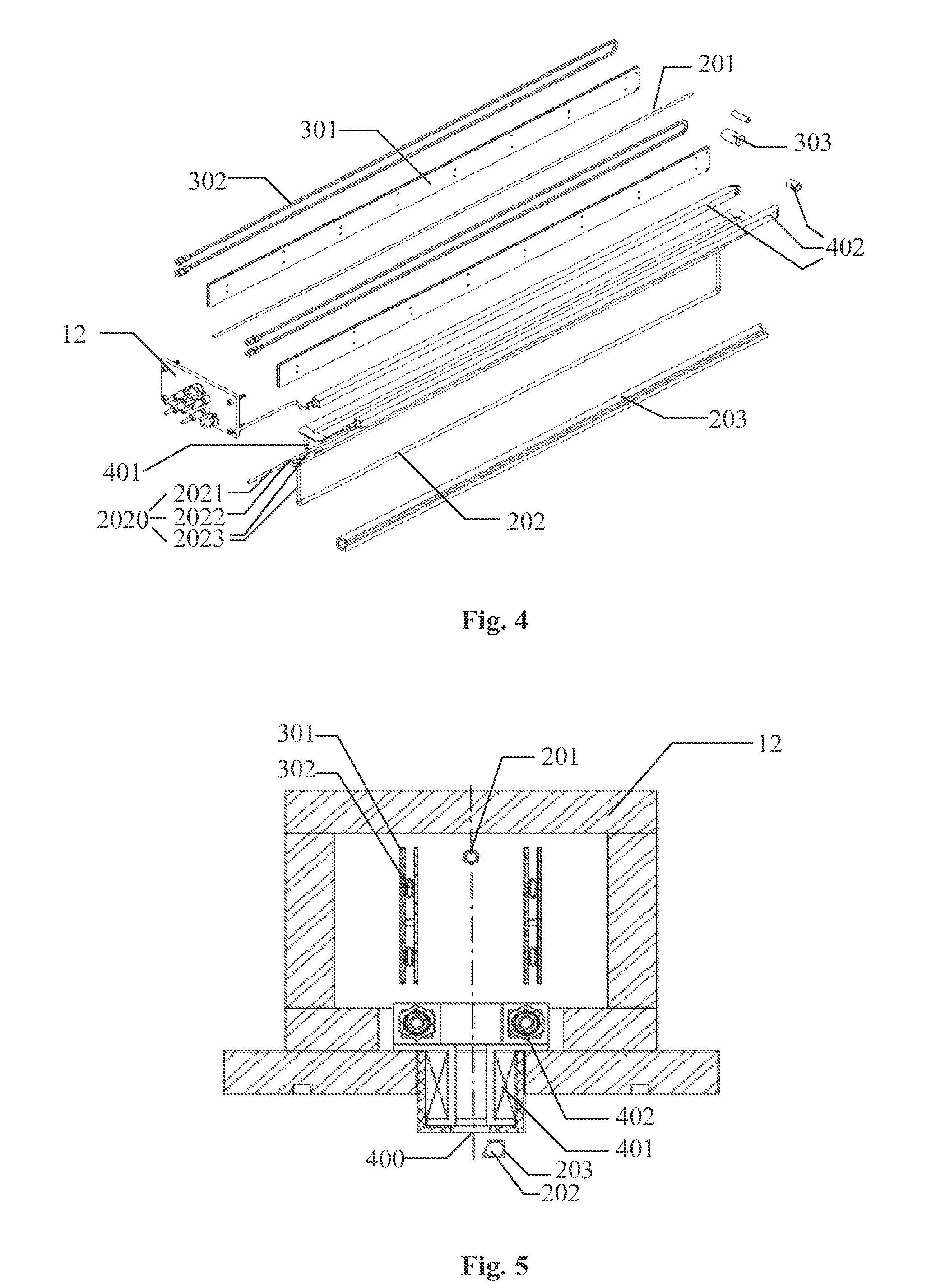
[0019]Referring to FIG. 1 to FIG. 5, FIG. 1 is a perspective schematic view of a plasma source according to an embodiment of the present application; FIG. 2 is a bottom schematic view of the plasma source according to the embodiment of the present application; FIG. 3 is a first exploded schematic view of the plasma source according...


PUM


Abstract

Embodiments of the present application disclose a linear plasma source applied to the field of solar cell production. A linear plasma source comprising a housing which forms a reaction chamber having an outlet; a gas intake system comprising an internal pipeline which is mounted on the housing and located inside the reaction chamber for releasing reaction gas into the reaction chamber; an electrode system comprising at least two electrode plates which are mounted on the housing and located around the internal pipeline within the reaction chamber; and an electromagnetism system comprising an electromagnetic coil, and the electromagnetic coil is mounted at the outlet of the reaction chamber of the housing and has a plasma outlet. The embodiments of the present application have a simple structure, a low production cost, a good uniformity and a high film compactness.

Description

[0001]The present application claims the benefit of priority to Chinese Patent Application No. 201310043635.5 titled “LINEAR PLASMA SOURCE”, filed with the Chinese State Intellectual Property Office on Feb. 4, 2013, the entire disclosure of which is incorporated herein by reference.FIELD OF THE INVENTION[0002]The present application relates to the field of solar cell production, and more to particular to a linear plasma source.BACKGROUND OF THE INVENTION[0003]With the advancement of technology, the application of solar cells is more and more widely, and in the process of film deposition or etching on silicon wafer of the solar cell, a linear plasma source is used to generate plasma for film deposition.[0004]In the prior art, linear plasma source mainly includes hollow cathode plasma source, microwave linear plasma source and so on. The microwave linear plasma source in the prior art has a duct connected to a device generating microwave, the duct is located in a reaction chamber, a d...

Claims


Application Information

Patent Timeline
IPC IPC(8): H01J37/32
CPCH01J37/3244H01J37/32091H01J37/321
Inventor CHEN, JIEXINXU, ZHIMINGLIU, YUEE
Owner SHENZHEN JT AUTOMATION EQUIP CO LTD
Learn More