System for detection of spaced droplets
a technology of space droplets and detection systems, applied in the field of detection systems of spaced droplets, can solve the problems of increasing costs, increasing instrument complexity, and emulsion-based assays presenting technical challenges for high-throughput testing
- Summary
- Abstract
- Description
- Claims
- Application Information
AI Technical Summary
Benefits of technology
Problems solved by technology
Method used
Image
Examples
example 1
Detection System 1
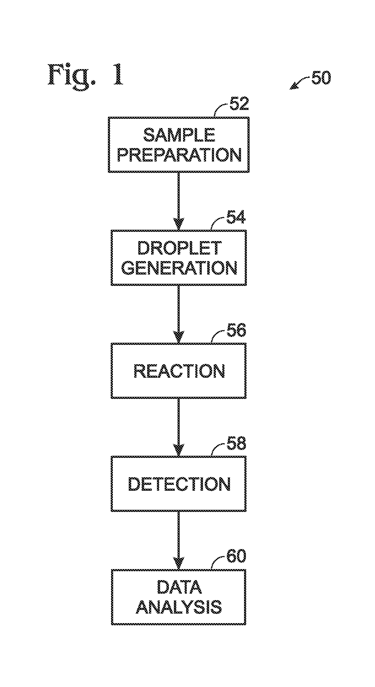
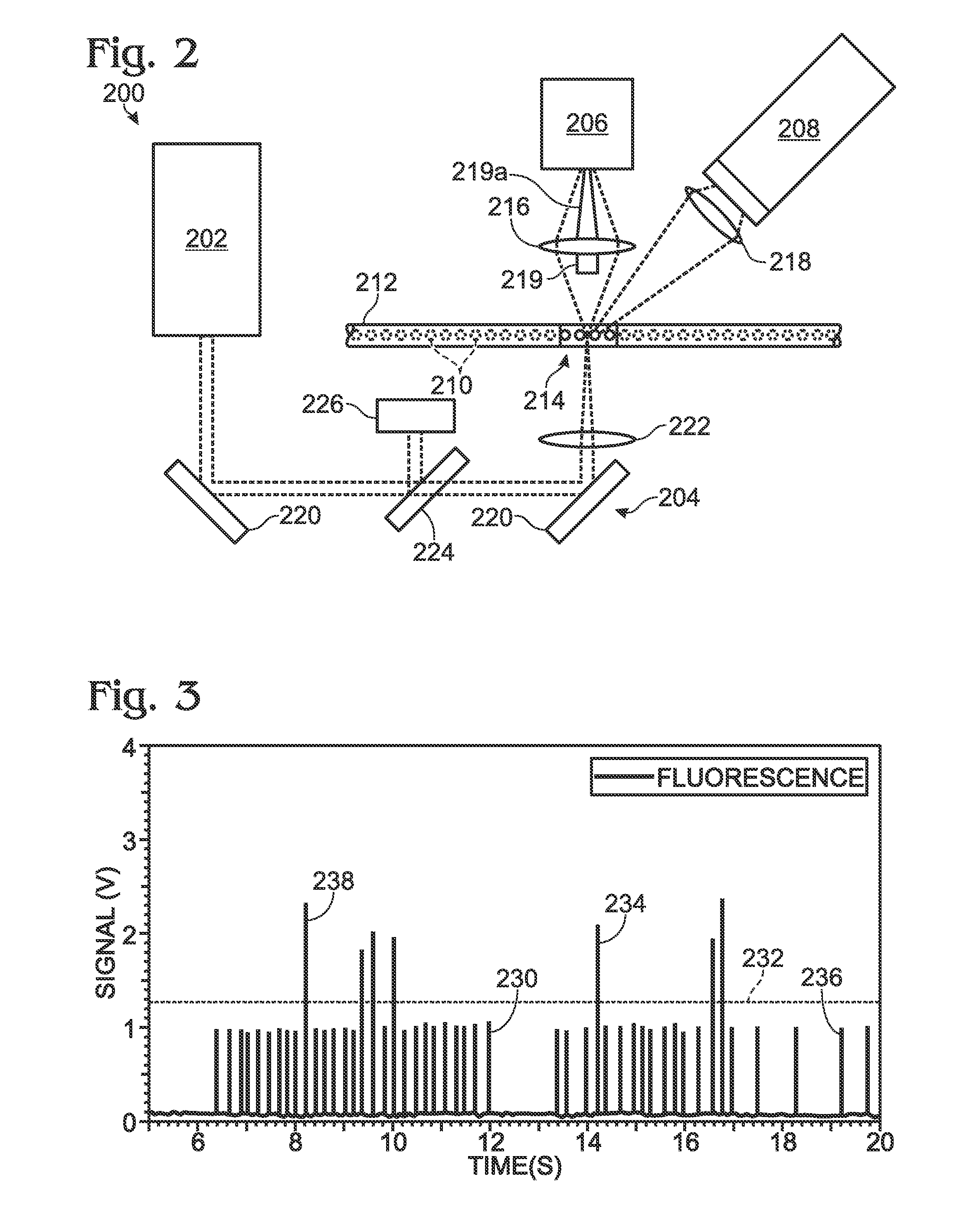
[0057]This example describes an optical detection system based on measuring the end-point fluorescence signal of each sample / reagent droplet after a PCR amplification process is complete. The exemplary system is suitable for making both qualitative and quantitative measurements; see FIGS. 2 and 3.
[0058]FIG. 2 depicts a detection system 200 configured to detect both scattered and fluorescence radiation. Detection system 200 includes a radiation source 202, transmission optics generally indicated at 204, a forward scatter detector 206, and a fluorescence detector 208. The forward scatter detector may be replaced or augmented, in some embodiments, by side and / or back scatter detectors, among others, configured to detect light scattered to the side or back of the sample, respectively. Similarly, the fluorescence detector may be replaced or augmented, in some embodiments, by an epi-fluorescence detector, among others, configured to detect fluorescence emitted anti-paral...
example 2
Detection Systems Using Optical Fibers
[0071]This example describes fluorescence detectors configured to measure the end-point fluorescence signal of sample / reagent droplet after PCR, and which utilize one or more optical fibers to transmit radiation to and / or from an intersection region within which illuminating radiation intersects the path of the sample-containing droplets. The exemplary systems are suitable for making both qualitative and quantitative measurements; see FIGS. 4-9.
[0072]FIG. 4 depicts an optical detection system, generally indicated at 250, which is similar to system 200 depicted in FIG. 2 except that transmission optics 204 of system 200 have been replaced by an optical fiber 254. Optical fiber 254 may be constructed from a glass, a plastic, and / or any other material that is substantially transparent to radiation of one or more particular desired wavelengths and configured to transmit that radiation along the length of the fiber, preferably with little or no loss ...
example 3
Detection Systems with Plural Radiation Channels
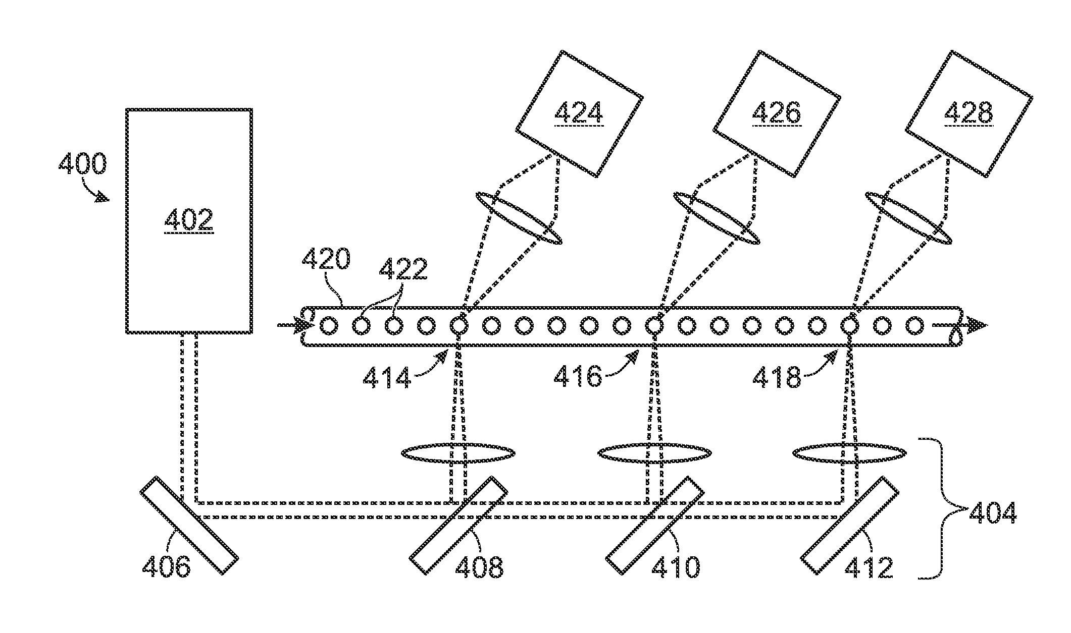
[0089]In some cases, a detection system according to the present disclosure may include multiple separate incident radiation channels to illuminate sample-containing droplets that have undergone PCR thermocycling. This example describes two such systems and some of their potential uses; see FIGS. 10 and 11.
[0090]FIG. 10 depicts a multi-channel cytometry-type optical detection system, generally indicated at 400. Detection system 400 includes a radiation source 402, configured to emit radiation at one or more desired wavelengths. As described previously, a radiation source according to the present disclosure may be of various types, such as an LED source or a laser source, and may emit radiation substantially at a single wavelength, at a plurality of substantially discrete wavelengths, or within one or more ranges of wavelengths.
[0091]Radiation from source 402 passes from the source toward transmission optics, as generally indicated at 4...
PUM
| Property | Measurement | Unit |
|---|---|---|
| diameters | aaaaa | aaaaa |
| diameters | aaaaa | aaaaa |
| diameters | aaaaa | aaaaa |
Abstract
Description
Claims
Application Information
 - R&D
- Intellectual Property
- Life Sciences
- Materials
- Tech Scout
- Unparalleled Data Quality
- Higher Quality Content
- 60% Fewer Hallucinations
Browse by: Latest US Patents, China's latest patents, Technical Efficacy Thesaurus, Application Domain, Technology Topic, Popular Technical Reports.
© 2025 PatSnap. All rights reserved.Legal|Privacy policy|Modern Slavery Act Transparency Statement|Sitemap|About US| Contact US: help@patsnap.com


