Eureka AIR delivers breakthrough ideas for toughest innovation challenges, trusted by R&D personnel around the world.

Multilayer inductor and power supply circuit module

a technology of inductor and power supply circuit, applied in the direction of coils, transformers/inductance details, inductances, etc., can solve the problems of short circuit failure, and achieve the effect of excellent characteristics

Active Publication Date: 2014-08-14
MURATA MFG CO LTD
View PDF20 Cites 25 Cited by
  • Summary
  • Abstract
  • Description
  • Claims
  • Application Information

AI Technical Summary

Benefits of technology

This patent describes a new type of inductor that can be used in power supply circuit modules. This inductor has multiple layers and is designed to have excellent characteristics. Its design allows for larger inductance and prevents the formation of dishes in the conductor surface. When used in a power supply circuit module, this inductor can handle larger currents and achieve a greater degree of flatness. Overall, this patent provides a solution for improving the performance of power supply circuit modules.

Problems solved by technology

However, since the shield member 220 is composed of a conductive material, top-surface-side portions of the external connection conductors 171P and 172P of the multilayer inductor 100P and solder that has spread onto these top-surface-side portions may come into contact with the shield member 220 and cause short circuit failures to occur.

Method used


Image

  • Multilayer inductor and power supply circuit module
  • Multilayer inductor and power supply circuit module
  • Multilayer inductor and power supply circuit module

Examples


Embodiment Construction

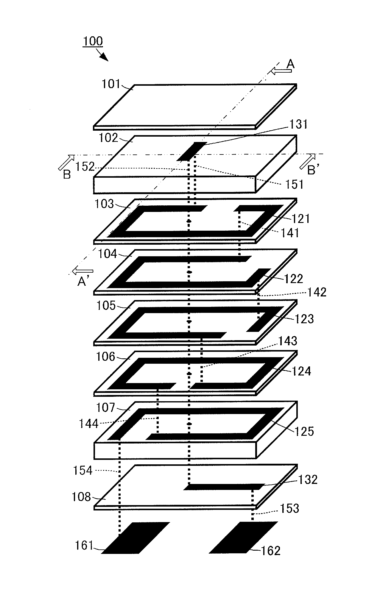
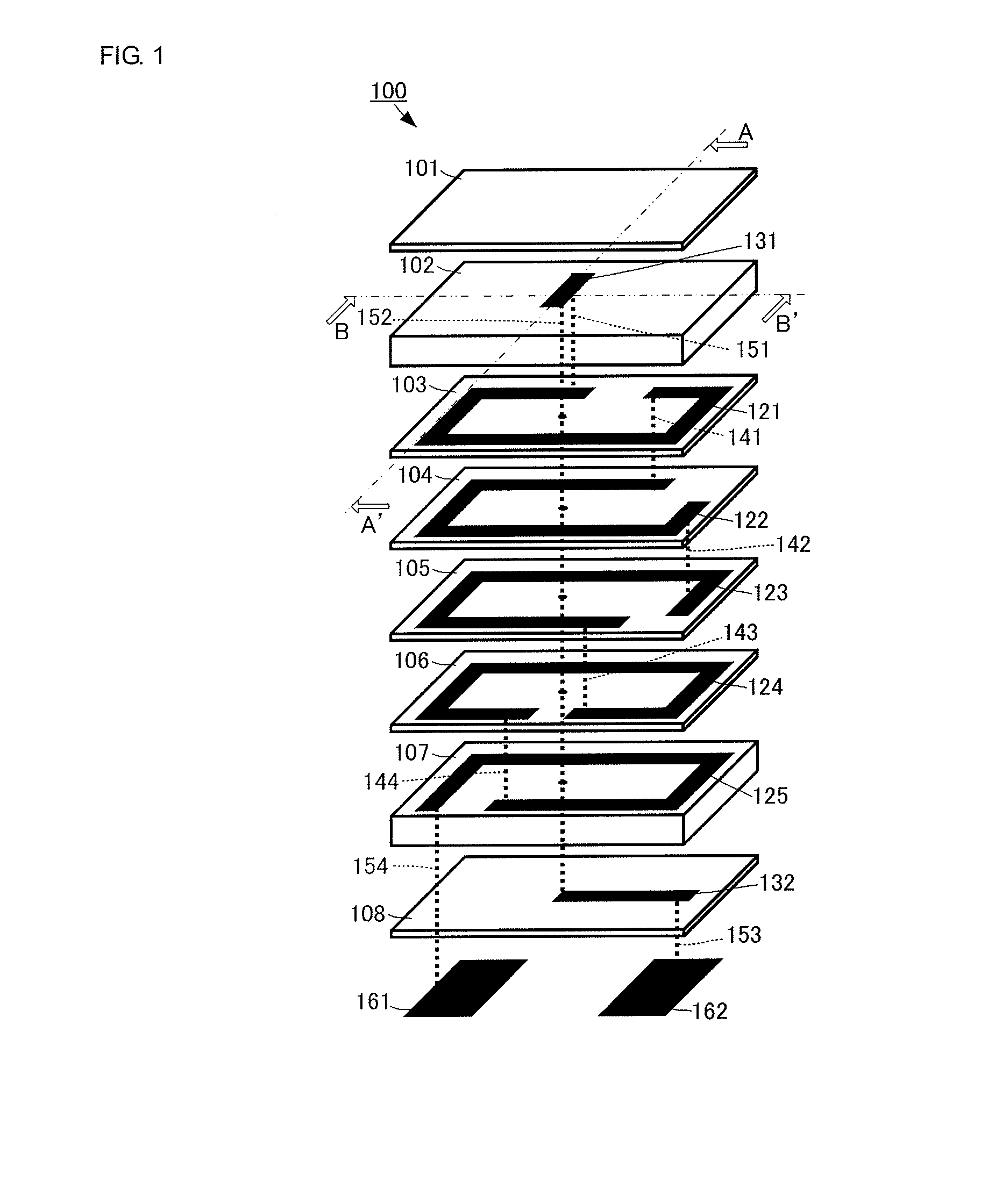
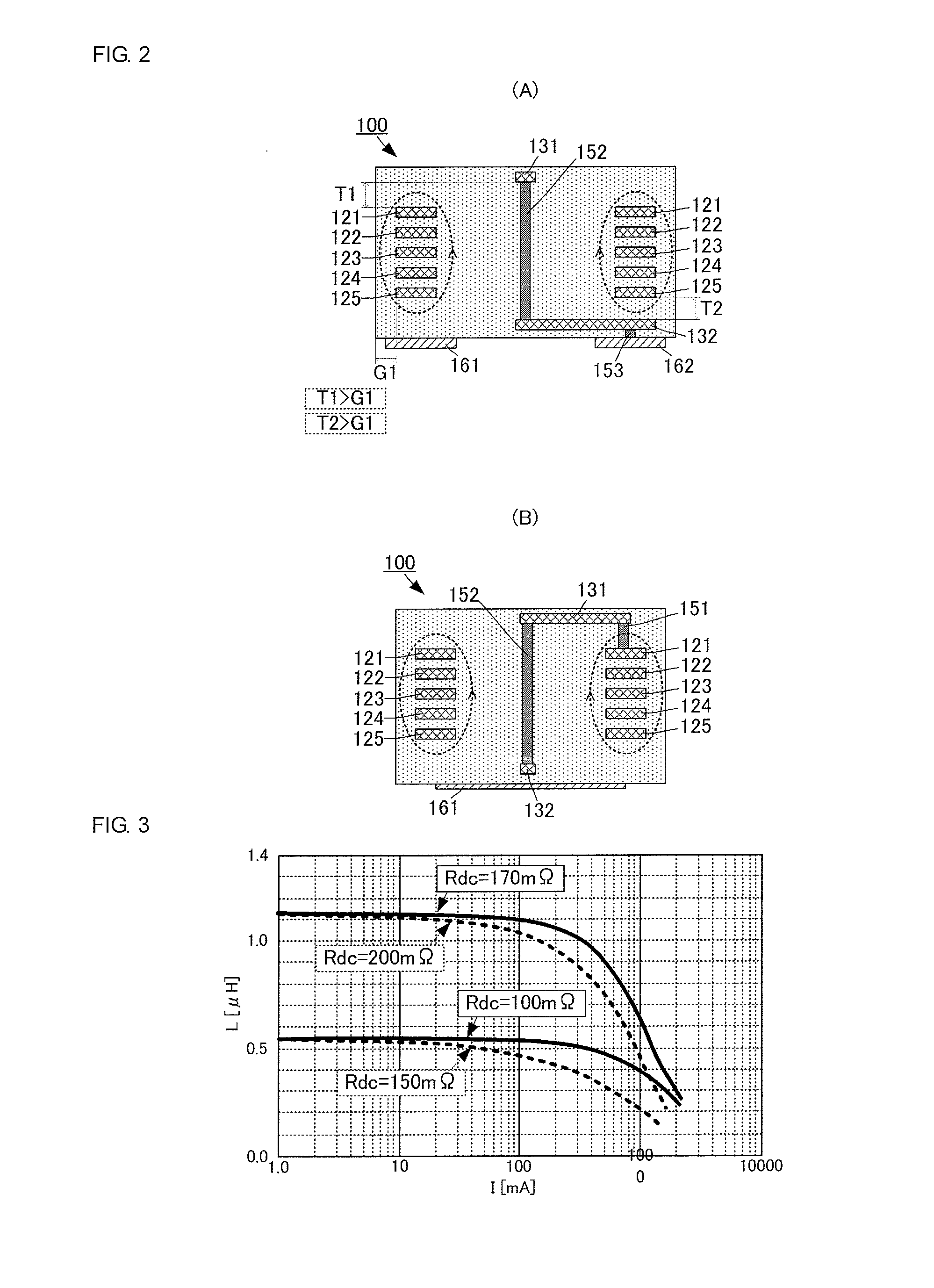
[0051]A multilayer inductor according to a first embodiment of the present invention will now be described with reference to the drawings. FIG. 1 is an exploded perspective view of a multilayer inductor 100 according to the first embodiment of the present invention. FIG. 2(A) is a sectional view taken along a cross section A-A′ in FIG. 1 for the multilayer inductor 100 according to the first embodiment of the present invention. FIG. 2(B) is a sectional view taken along a cross section B-B′ in FIG. 1 for the multilayer inductor 100 according to the first embodiment of the present invention.

[0052]The multilayer inductor 100 is a so-called land grid array (LGA) type inductor and includes a multilayer body, inside of which a coil conductor is formed, and external connection conductors 161 and 162 formed on a bottom surface of the multilayer body.

[0053]The external connection conductors 161 and 162 are rectangular flat plate conductors having a certain area. The external connection condu...


PUM


Abstract

A multilayer inductor includes a multilayer body formed by stacking magnetic layers on top of one another. Loop-like line-shaped conductors are respectively formed on the magnetic layers. The loop-like line-shaped conductors are connected to one another by interlayer connection conductors, and thereby a coil conductor having an axis extending in the stacking direction is formed. One end of the line-shaped conductor, which is an uppermost-layer-side end portion of the coil conductor, is connected to a line-shaped conductor, which is for routing and is formed on a higher layer, by a interlayer connection conductor. The line-shaped conductor is connected to an interlayer connection conductor that is formed so as to penetrate through substantially the center inside the loop-like line-shaped conductors. The interlayer connection conductor is connected to an external connection conductor on a bottom surface of the multilayer body via a line-shaped conductor and an interlayer connection conductor.

Description

CROSS REFERENCE TO RELATED APPLICATIONS[0001]The present application is a continuation of PCT / JP2012 / 076883 filed Oct. 18, 2012, which claims priority to Japanese Patent Application No. 2012-042659, filed Feb. 29, 2012, the entire contents of each of which are incorporated herein by reference.FIELD OF THE INVENTION[0002]The present invention relates to a multilayer inductor including an inductor formed by forming a spiral-shaped conductor in a multilayer body.BACKGROUND OF THE INVENTION[0003]To date, various surface mount inductors have been proposed in order to form compact power supply circuits. For example, in Patent Document 1, an inductor is disclosed that has an external connection terminal formed at each of the two opposing ends of a rectangular-parallelepiped-shaped multilayer body. An inductor composed of a spiral-shaped conductor is formed inside the multilayer body. One end of the inductor is connected to one of the external connection terminals and the other end of the i...

Claims


Application Information

Patent Timeline
IPC IPC(8): H01F27/28
CPCH01F2027/2809H01F27/2804H01F17/0013H01F17/0033H01F27/292
Inventor YAZAKI, HIROKAZU
Owner MURATA MFG CO LTD
Why Eureka
Eureka Blog
Learn More