Resonance-based single inductor output-driven dc-dc converter and method

a dc-dc converter and output technology, applied in the field of dc-dc converters, can solve the problems of high cost of external inductors required for each dc-dc voltage converter, inability to add a large number of dc-dc converters to provide different power supply voltages in various parts of the chip, and the simo dc-dc converters presently available, etc., to achieve the effect of reducing system cost, reducing system power efficiency

Active Publication Date: 2014-08-21
TEXAS INSTR INC
View PDF7 Cites 41 Cited by
  • Summary
  • Abstract
  • Description
  • Claims
  • Application Information

AI Technical Summary

Benefits of technology

[0026]It is another object of the invention to provide a resonant DC-DC converter which allows higher system power efficiency and lower system cost than is the case in prior DC-DC converters having somewhat comparable performance.
[0027]It is another object of the invention to provide a resonant SIMO DC-DC converter which allows higher system power efficiency and lower system cost than is the case in prior SIMO DC-DC converters having somewhat comparable performance.
[0028]It is another object of the invention to provide a resonant SIMO DC-DC converter which has lower cross-regulation, higher power efficiency for a given SIMO DC-DC converter package volume, and lower cost than prior SIMO DC-DC converters having somewhat comparable performance and than prior SISO DC-DC converters having somewhat comparable performance.

Problems solved by technology

Unfortunately, adding a large number of DC-DC converters to provide different power supply voltages in various parts of the chip usually is not practical because that has required adding a corresponding number of external inductors and capacitors and associated package leads, which is very costly.
Consequently, and as a practical matter at the present state-of-the-art, only seven or eight separate power supply voltages ordinarily are provided on a relatively large chip, and only one or two separate power supply voltage circuits are provided on a relatively small chip because of the high cost of the external inductors required for each DC-DC voltage converter.
Unfortunately, the best SIMO DC-DC converters presently available have a number of drawbacks, including lower power efficiency and higher cost than using an equivalent number of SISO (Single Input, Single Output) DC-DC converters.
This is because of various complex problems associated with sharing power supply energy produced at a single output among a number of outputs.
However, if bucket 7 is over-filled (i.e., inductor L is overcharged), there is a loss or waste of energy.
The phenomenon of under-filling or under-charging the inductor and not being able to supply enough charge to each of the outputs during a given cycle is called “cross regulation”, and this is a basic problem for SIMOs.
Load regulation problems may prevent accurate voltage regulation of at least some of the output power supply voltages VOUT1, 2, . . . 5.
Prior SIMO DC-DC converters have lower power efficiency than SISO DC-DC converters when the inductor L is “overcharged”.
A SIMO converter needs to deal with the sharing of charge / current from the single inductor and that reduces the DC-DC converter efficiency.
Another problem of prior SIMO DC-DC converters is that they include an additional input switch that inherently reduces power efficiency, because each input switch is coupled in series between the input and the multiple outputs, respectively, of the output of the SIMO DC-DC converter.
That adds both conductive power loss and switching power loss for each output switch transistor, and also increases EMI (electromagnetic interference) due to operating the various switch transistors.
Both input switch MP and the selected output switch dissipate a significant amount of power.
The output capacitors CL1, 2, . . . N are relatively large, which is undesirable because they add substantially to the total system cost.
Most of current state of the art switch-based resonant converters have several drawbacks that make them less desirable than standard DC-DC converters.
These drawbacks include higher RMS current in the inductor, higher voltage seen by power switches (sometimes more than double the input voltage seen by the power switches), and limited power density output.
The use of SIMO DC-DC converters therefore potentially allows higher system power efficiency and reduced system cost, but unfortunately, the cost of present state-of-the-art SIMO DC-DC converters is high.
They also generate high EMI (electromagnetic interference) have cross-regulation problems.

Method used


Image

  • Resonance-based single inductor output-driven dc-dc converter and method
  • Resonance-based single inductor output-driven dc-dc converter and method
  • Resonance-based single inductor output-driven dc-dc converter and method

Examples


Embodiment Construction

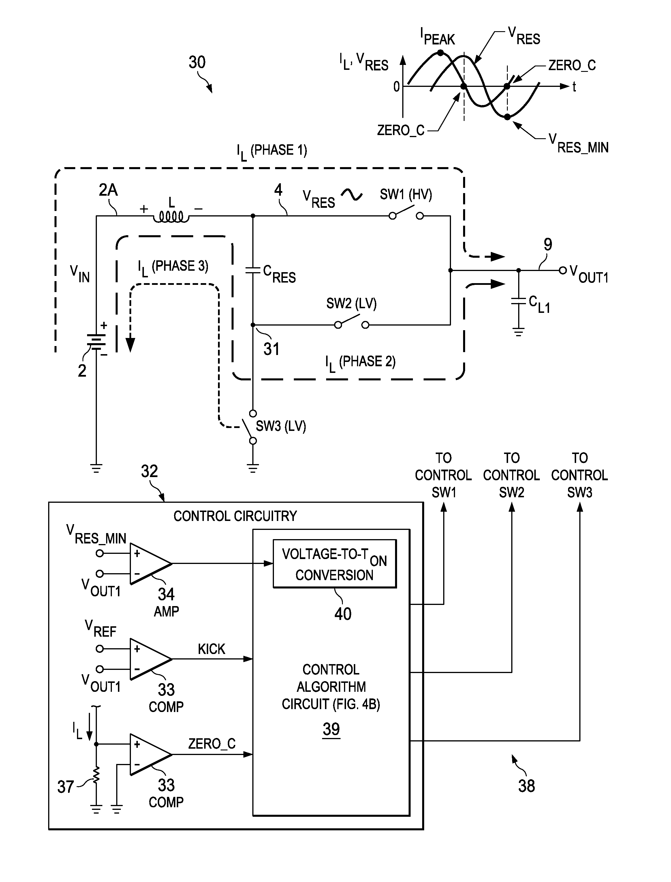
[0073]An optimum DC-DC converter topology preferably has “soft switching”, i.e., ZVS (zero voltage switching) and ZCS (zero current switching) wherein switching of a typical MOS switch transistor therein is performed only when both the source and drain terminals are at essentially the same voltage. However, most DC-DC converters include at least one “non-ZVS” switching transistor, which typically is the “high side” input switch transistor. (A “high side” input switch is connected to the positive supply voltage and a “low side” input switch is connected to ground.) An input switch transistor supplies current to the external inductor of a typical DC-DC converter. One reason that ZVS switching is not commonly used in DC-DC converters is that most of them do not use “resonant techniques” such as those mentioned previously. (In a resonant DC-DC converter, the current flow through inductor L is bidirectional, rather than unidirectional as in non-resonant DC-DC converters. The operating mo...


PUM


Abstract

A resonance-based DC-DC converter for converting a DC input voltage to a first DC output voltage (VOUT1) on a output conductor (9) includes an inductor (L) having a first terminal connected to a source (2) of a DC input voltage (VIN) and a second terminal coupled to a first conductor (4) and a capacitor (CRES) having a first terminal coupled to the first conductor. A first switch (SW1) is coupled between the resonance conductor and the output conductor to conduct inductor current (IL) into the output conductor during a first phase (Phase1). A second switch (SW2) is coupled between a second terminal of the capacitor and the output conductor to conduct inductor current through the capacitor into the output conductor (9) during a second phase (Phase2). A third switch (SW3) is coupled between the second terminal (31) of the capacitor and a first reference voltage (GND) to conduct inductor current from a source of the first reference voltage through the capacitor to the input voltage (VIN) during a third phase (Phase3).

Description

[0001]This application claims the benefit of prior filed co-pending U.S. provisional application Ser. No. 61 / 767,474 filed Feb. 21, 2013, entitled “Resonance-Based Single Inductor Output Driven DC-DC Converter and Method”, by Ranjit Kumar Dash and Keith E. Kunz, and incorporated herein by reference.BACKGROUND OF THE INVENTION[0002]The present invention relates generally to DC-DC converters, and more particularly to circuitry and methods which substantially increase the conversion efficiency and reduce costs of SIMO (single inductor multiple output) DC-DC converters.[0003]It should be understood that DC-DC converter technology has improved relatively slowly, but the advent of large, powerful computing devices on a single integrated circuit chip and the need to reduce their power consumption (especially in mobile devices) has led to the need for multiple on-chip power sources to provide a range of relatively high power supply voltages to various faster, higher-performance portions of ...

Claims


Application Information

Patent Timeline
Patent Type & Authority Applications(United States)
IPC IPC(8): H02M3/158H02M3/10
CPCH02M3/10H02M3/158H02M1/0058H02M1/009Y02B70/10
Inventor DASH, RANJIT K.KUNZ, KEITH E.
Owner TEXAS INSTR INC
Why Eureka
Try Eureka