Optocoupler Arrangement and Input and/or Output Module

Inactive Publication Date: 2014-08-28
SIEMENS AG
View PDF0 Cites 5 Cited by
  • Summary
  • Abstract
  • Description
  • Claims
  • Application Information

AI Technical Summary

Benefits of technology

[0009]It is an object of the present invention to provide an optocoupler arrangement or

Problems solved by technology

When actuating two series-connected optocouplers, the same po

Method used


Image

  • Optocoupler Arrangement and Input and/or Output Module
  • Optocoupler Arrangement and Input and/or Output Module
  • Optocoupler Arrangement and Input and/or Output Module

Examples


Example

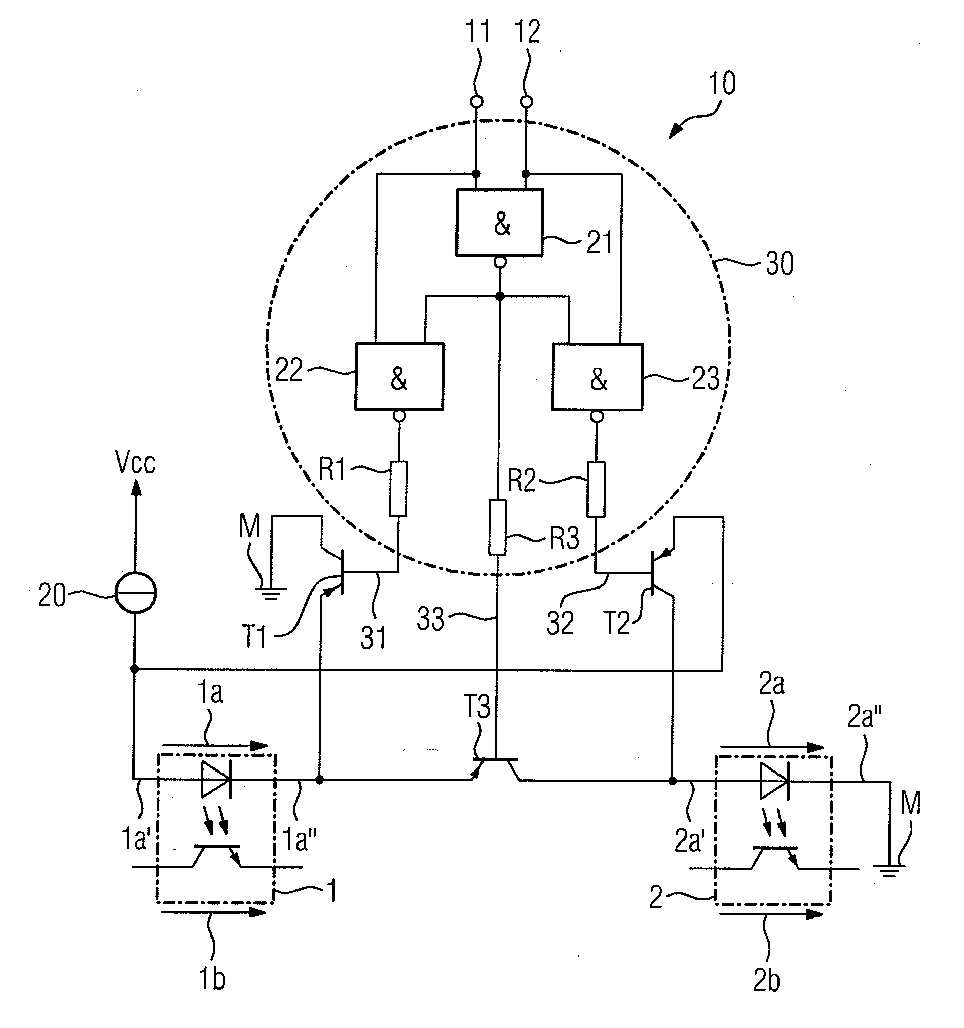
[0025]With reference to FIG. 1, shown therein is an optocoupler arrangement 10 for signal transmission during galvanic separation. Signals that may be present across a first signal input 11 and a second signal input 12, are to be forwarded, in a galvanically separated manner, by a first optocoupler 1 and a second optocoupler 2. To this end, the first optocoupler 1 has a first input path 1a and a first output path 1b, and the second optocoupler 2 has a second input path 2a and a second output path 2b.

[0026]If current is flowing through the first input path 1a, the first optocoupler 1 is activated and a current flow can likewise occur in the first output path 1b, if current is flowing through the second input path 2a of the second optocoupler 2, the second optocoupler 2 is activated and a current can likewise flow in the second output path 2b.

[0027]The first input path 1a and the second input path 2a are arranged with a connecting switching device T3 in a series circuit, the connect...


PUM


Abstract

An optocoupler arrangement for signal transmission with galvanic separation includes a first optocoupler with a first input path and a first output path, a second optocoupler with a second input path and a second output path, wherein the first and second input paths are arranged in series with a connecting switching device, and wherein an actuation circuit has first and second input signals as inputs, and first, second and third outputs as outputs, and the actuation circuit is configured such that, as a function of a first switching state related to the first and second signal inputs, the connecting switching device is actuated, and with respect to either a second or a third switching state, either a first switching device assigned to the first input path of the first optocoupler or a second switching device assigned to the second input path of the second optocoupler is actuated.

Description

BACKGROUND OF THE INVENTION[0001]1. Field of the Invention[0002]The invention relates to an optocoupler arrangement for signal transmission with galvanic separation, and to an input and / or output module within industrial automation technology having input and / or output channels, where the channels have the optocoupler arrangement.[0003]2. Description of the Related Art[0004]An optocoupler is an electronic component and is used to transmit a signal between two galvanically separated current circuits. An optocoupler preferably includes an optical sensor, such as a light-emitting diode, and an optical receiver, such as a photo transistor, which are preferably accommodated in a light-impermeable housing.[0005]EP 1 770 457 B1 discloses an optocoupler arrangement for the galvanic separation of signals. EP 1 770 457 B1 also describes a peripheral module, such as an input or output module, for an automation device, which has this optocoupler arrangement.[0006]In electronic modules, in which...

Claims


Application Information

Patent Timeline
IPC IPC(8): H04B10/80
CPCH04B10/802G05B19/05H03K19/00353G05B2219/33204G05B19/054H03K17/605
Inventor HOLTZ, STEFAN
Owner SIEMENS AG
Why Eureka
Try Eureka