

Isolated boost flyback power converter
- Summary
- Abstract
- Description
- Claims
- Application Information
AI Technical Summary
Benefits of technology
Problems solved by technology
Method used
Image

Examples
first embodiment
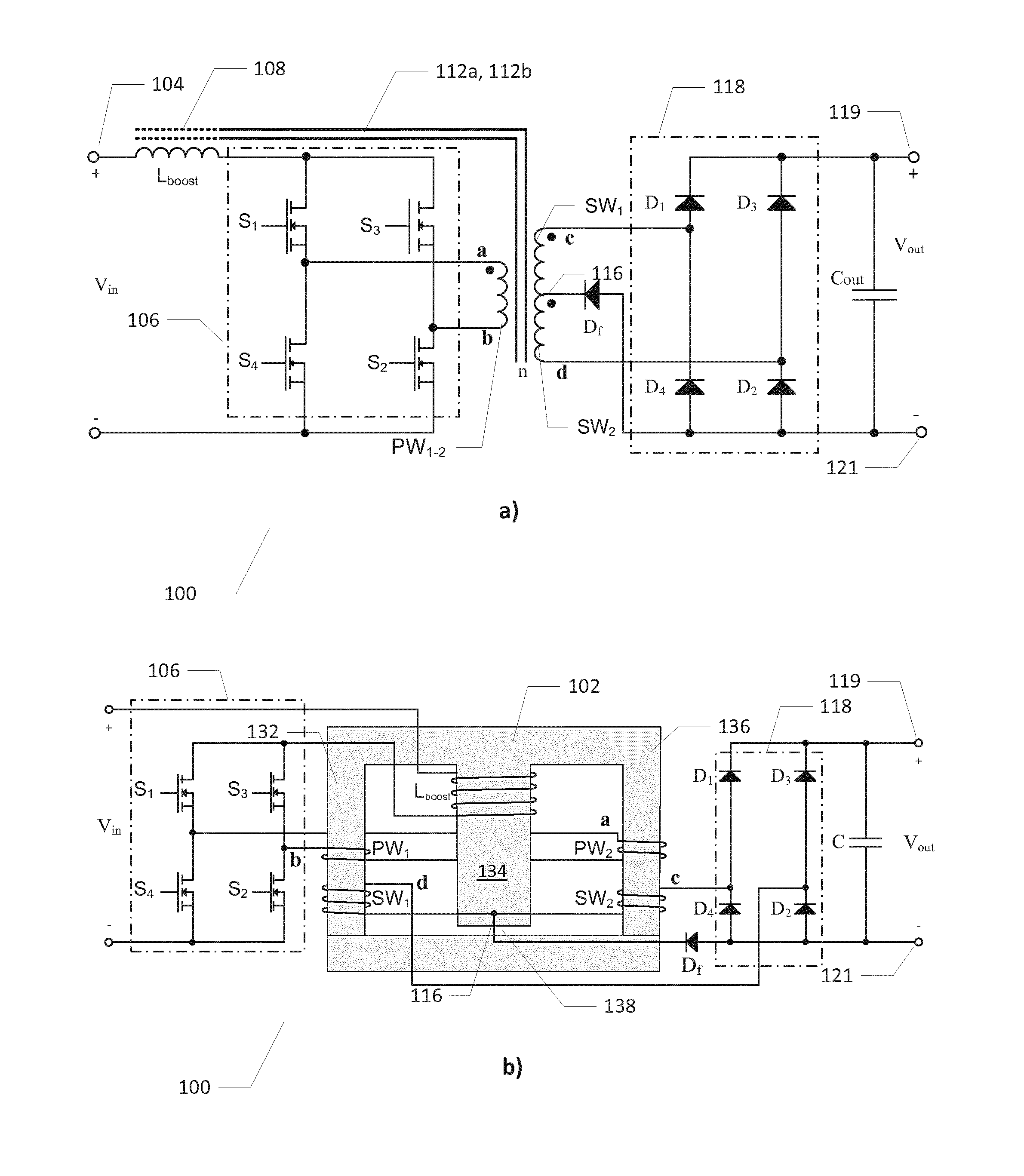
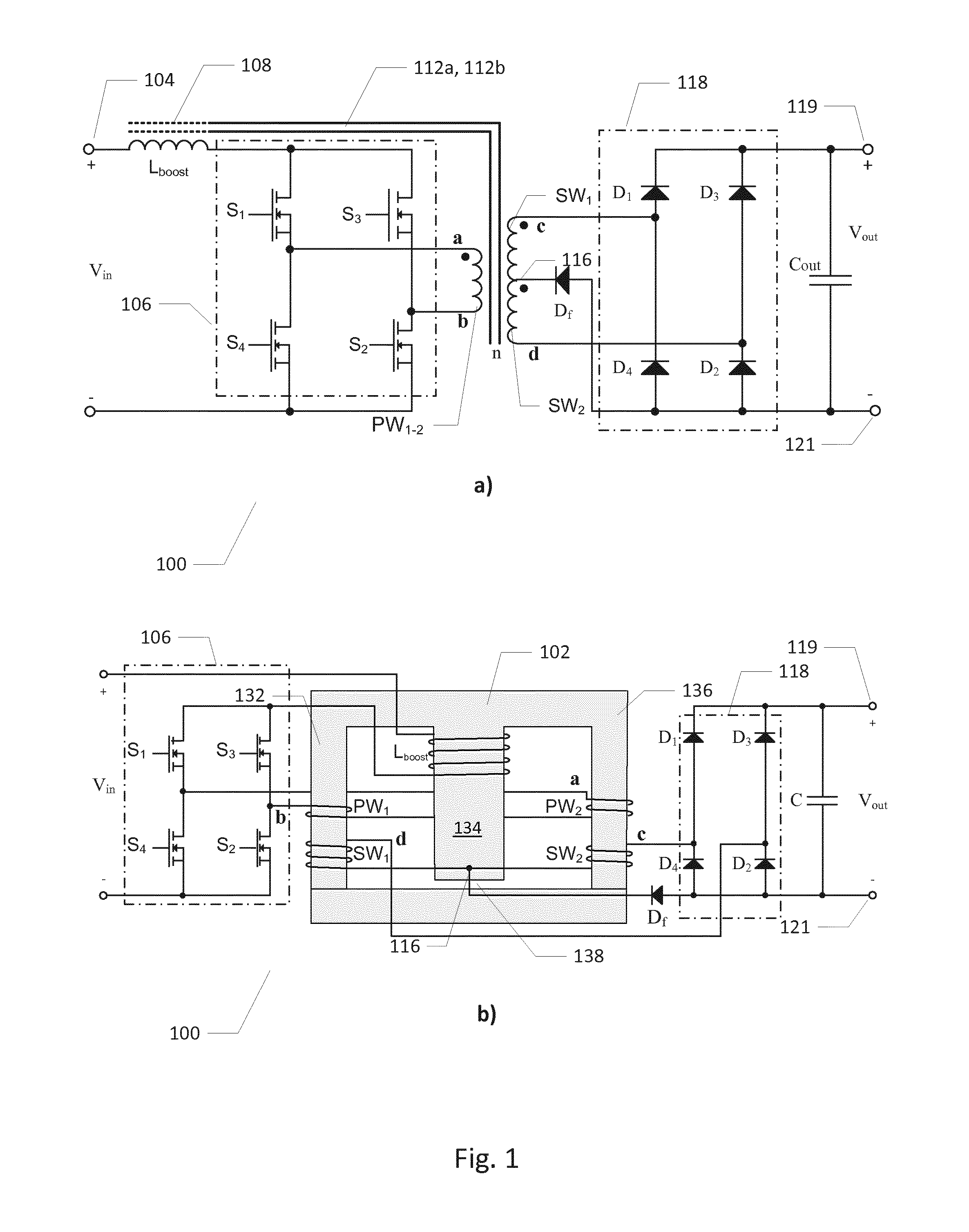
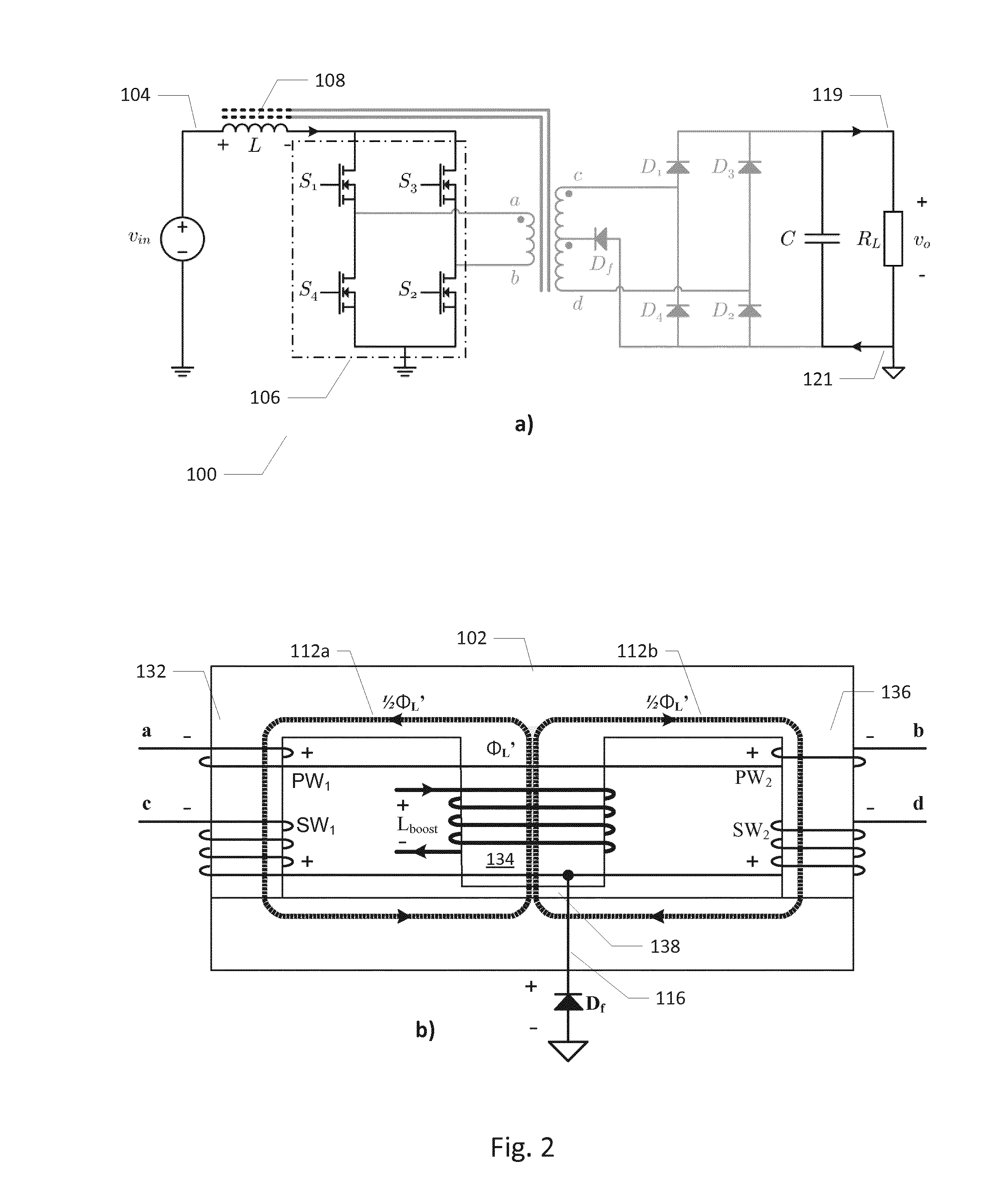
[0044]FIG. 1a) illustrates schematically an electrical circuit diagram of an isolated boost power converter 100 in accordance with the present invention. The isolated boost power converter 100 comprises a magnetically permeable multi-legged core in form of a three legged El core 102. The three legged El core 102 comprises a center leg 134 surrounded by a first outer leg 132 and a second outer leg 136 in a mirror-symmetrical layout or structure about a central vertical axis extending through the center leg 134. The center leg 134 comprises an air gap 138 which allows magnetic energy of a boost inductor, Lboost, to be stored therein. The isolated boost power converter 100 comprises an input terminal 104 for receipt of an input voltage, Vin. The input voltage may be a DC voltage between 5 Volt and 100 Volt. The boost inductor, Lboost, is arranged or wound around the center leg 134 of the three legged El core 102 and electrically coupled between the input terminal 104 and a transistor d...
second embodiment
[0056]FIG. 6a) is an electrical circuit diagram of an isolated boost power converter 600 in accordance with the invention. The isolated boost power converter 600 is similar to the previously described isolated boost converter 100 except for the reversal of the polarity of the rectifying diode Df and an accompanying reversal of a winding orientation of the boost inductor Lboost relative to the winding orientation depicted on FIG. 1b). Like features have been marked with corresponding numerals to assist the comparison. The skilled person will notice that this configuration of the rectifying diode Df works similarly to the above-described configuration, in that when the primary transformer winding is inactive, a decreasing flux in the center leg will cause Df to be forward biased in either case.
[0057]FIG. 6b) is an electrical circuit diagram 640 of an isolated boost power converter with a center-tapped rectification circuit 648 in accordance with a third embodiment of the invention. Th...
fourth embodiment
[0058]FIG. 7 is an electrical circuit diagram of an isolated boost power converter 700 with a dual core topology comprising an integrally formed multi-legged El core 702a, 702b in accordance with the invention. The isolated boost power converter 700 comprises an integrally formed magnetically permeable multi-legged core in form of a first three legged El core 702a and a second three legged El core 702b that share a common “I” leg 740 such that the entire magnetically permeable multi-legged core is a unitary structure. The structure of the integral magnetically permeable multi-legged core 702a, 702b is mirror symmetrical about a horizontal symmetry axis 750. Each of the El cores 702a, 702b comprises a center leg 734a, 734b, respectively, surrounded by a first outer leg 732a,b and a second outer leg 736a,b in a mirror-symmetrical layout or structure about a central vertical axis extending through a middle of the center legs 734a, 734b.
[0059]Each of the center legs 734a, 734b comprise...
PUM
 Abstract
Description
Claims
Application Information