Metal Lattice Production Method, Metal Lattice, X-Ray Imaging Device, and Intermediate Product for Metal Lattice

Inactive Publication Date: 2014-08-28
KONICA MINOLTA INC
View PDF1 Cites 41 Cited by
  • Summary
  • Abstract
  • Description
  • Claims
  • Application Information

AI Technical Summary

Benefits of technology

[0011]In the metal grating structure manufacturing method of the present invention, after a concave part having an insulating layer on an inner surface thereof is formed in a silicon substrate, a portion of the insulating layer formed on a bottom part of the concave part is removed, and the silicon substrate at the bottom part of the concave part is etched to increase the surface area of the bottom part of the concave part as compared with a state before the etching, followed by filling the concave part with metal by an electroforming method. The metal grating structure manufacturing method is advantageous in finely form

Problems solved by technology

It is not easy to manufacture a structure having such a high aspect ratio.
This requires a certain time and involves a

Method used


Image

  • Metal Lattice Production Method, Metal Lattice, X-Ray Imaging Device, and Intermediate Product for Metal Lattice
  • Metal Lattice Production Method, Metal Lattice, X-Ray Imaging Device, and Intermediate Product for Metal Lattice
  • Metal Lattice Production Method, Metal Lattice, X-Ray Imaging Device, and Intermediate Product for Metal Lattice

Examples


Embodiment Construction

[0029]In the following, an embodiment of the present invention is described referring to the accompanying drawings. Constructions identified by the same reference numerals in the drawings are the same constructions and not repeatedly described unless necessary. Further, in the specification, in the case where the elements are generically referred to, the elements are indicated with reference numerals without suffixes, and in the case where the elements are individually referred to, the elements are indicated with reference numerals with suffixes.

[0030](Metal Grating Structure)

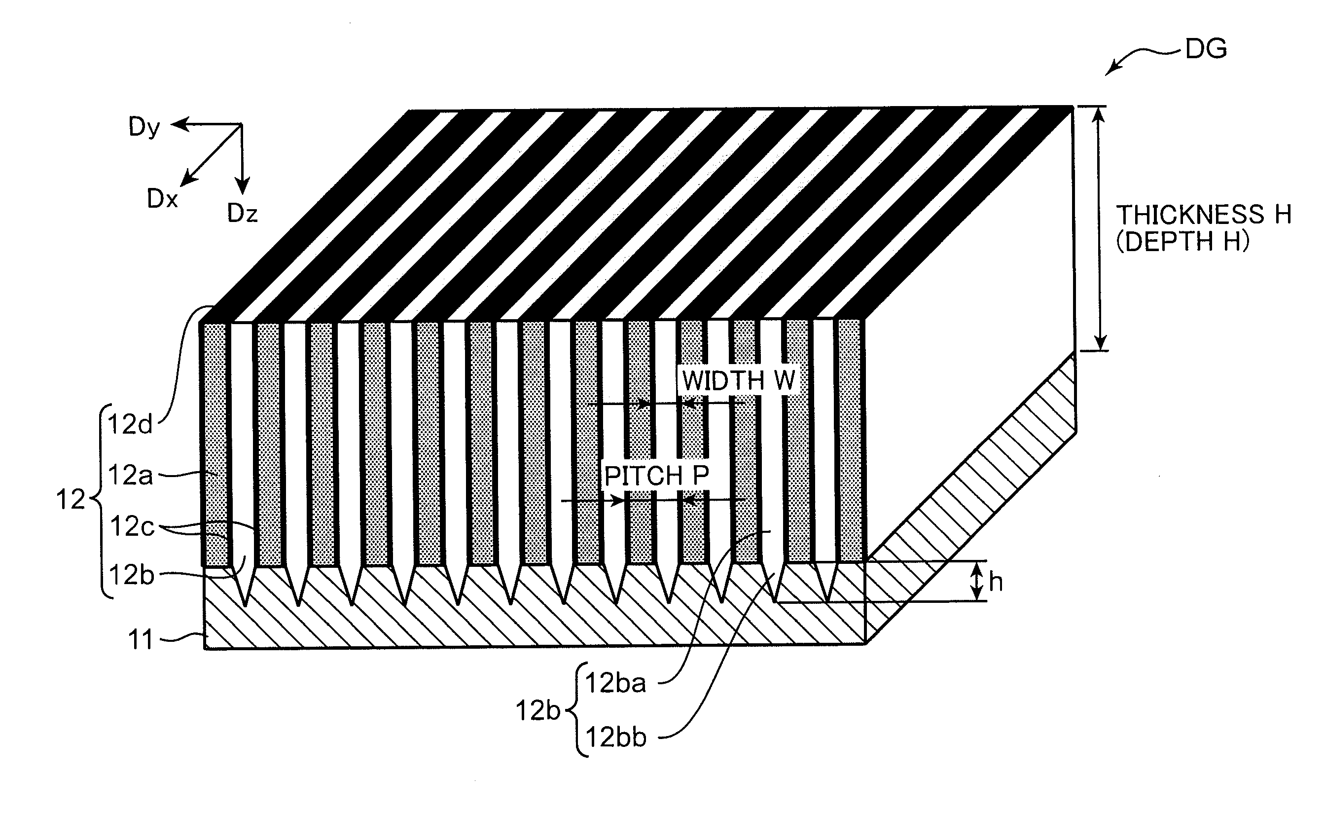
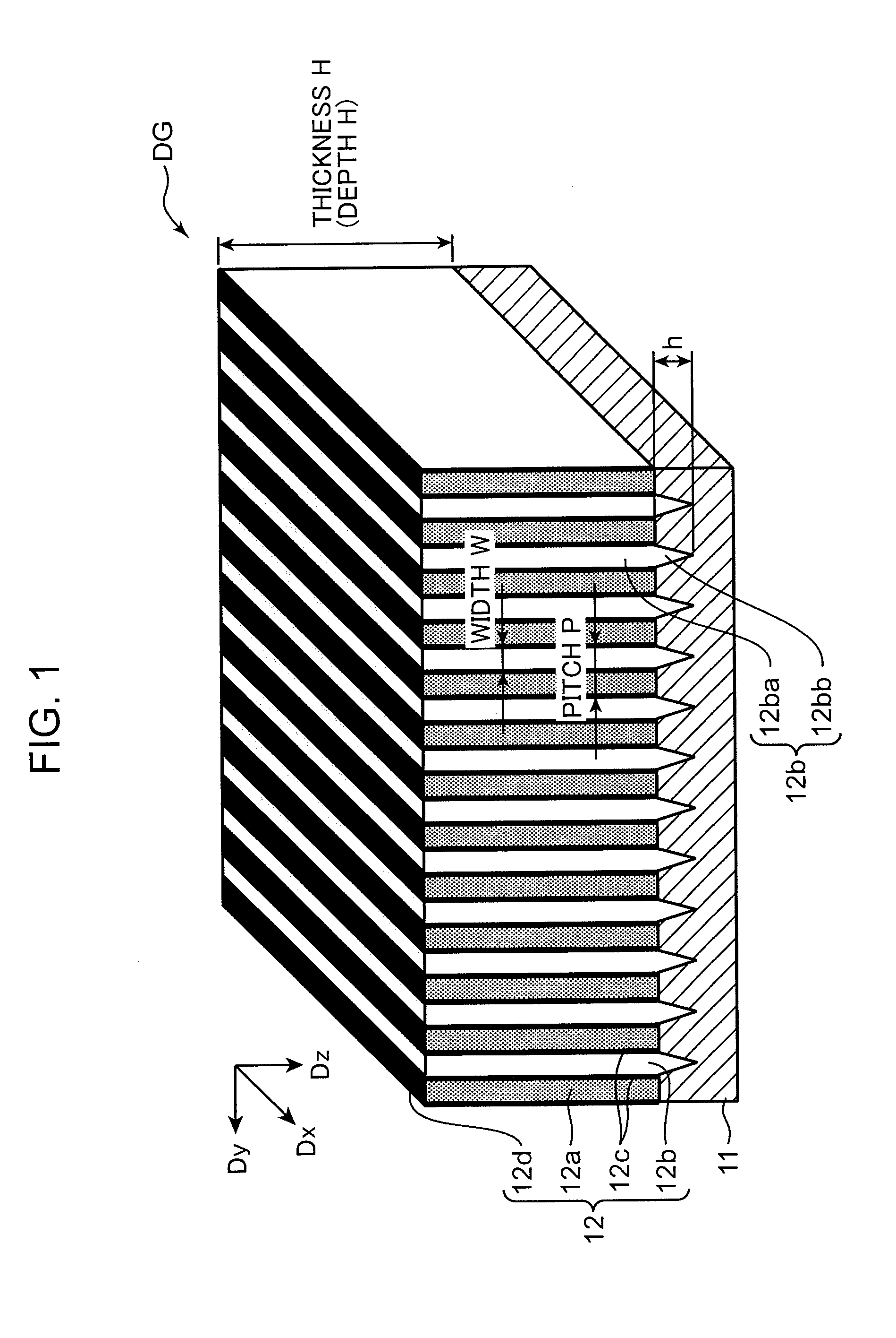
[0031]FIG. 1 is a perspective view showing a configuration of a metal grating structure according to an embodiment. As shown in FIG. 1, a metal grating structure DG according to the embodiment is provided with a first silicon part 11, and a grating portion 12 formed on the first silicon part 11. As shown in FIG. 1, the first silicon part 11 has a plate form or a layer form extending along the DxDy plane, in the...


PUM

PropertyMeasurementUnit
Depthaaaaaaaaaa
Surface areaaaaaaaaaaa

Abstract

Method for manufacturing a metal grating structure, wherein, after a concave part having an insulating layer on an inner surface thereof is formed in a silicon substrate, a portion of the insulating layer formed on a bottom part of the concave part is removed, and the silicon substrate at the bottom part of the concave part is etched to increase the surface area of the bottom part of the concave part as compared with a state before the etching, followed by filling the concave part with metal by an electroforming method.

Description

TECHNICAL FIELD[0001]The present invention relates to a method for manufacturing a metal grating structure for manufacturing a grating suitably used for, for instance, a Talbot interferometer or a Talbot-Lau interferometer. The present invention also relates to a metal grating structure manufactured by the manufacturing method, and an X-ray imaging device incorporated with the metal grating structure. The present invention also relates to an intermediate product for a metal grating structure for use in manufacturing the metal grating structure.BACKGROUND ART[0002]Diffraction gratings are utilized in optical systems of various devices, as a spectral element provided with multitudes of parallel periodic structures. In recent years, diffraction gratings are also applied to X-ray imaging devices. Diffraction gratings are roughly classified into transmissive diffraction gratings and reflective diffraction gratings according to diffraction methods. The transmissive diffraction gratings in...

Claims


Application Information

Patent Timeline
IPC IPC(8): G01N23/20C25D5/34
CPCA61B6/4035A61B6/4291A61B6/484G01N23/20008G01N23/20075C25D5/022C25D7/12C25D11/32C25D5/34G01N2223/315G21K1/025G21K2207/005C25D7/123G21K1/06
Inventor YOKOYAMA, MITSURU
Owner KONICA MINOLTA INC
Why Eureka
Try Eureka