Vacuum pump with rotor-stator positioning to provide non-return

Inactive Publication Date: 2014-08-28
FORD GLOBAL TECH LLC
View PDF4 Cites 1 Cited by
  • Summary
  • Abstract
  • Description
  • Claims
  • Application Information

AI Technical Summary

Benefits of technology

The patent describes a vacuum pump used in motor-vehicle engines. The pump is made up of a rotating vane and a stator with a passage for air to enter and exit. The rotor has a flexible element that can open and close the passage. This design reduces the resistance to lubricant oil discharge, which results in lower pressure between the inlet and outlet chambers at the end of the pumping cycle. This reduces the noise and misalignment that can occur with other types of vacuum pumps.

Problems solved by technology

The inventors herein have found that the limited opening extent of the shutter, together with its somewhat large restoring force, results in excessive lubricant oil pressure in the outlet chamber at the end of each pumping cycle.
Under some conditions, the high pressure of the outlet chamber relative to the inlet chamber causes misalignment or rocking of the rotor.
This, in turn, may cause the rotor to impact the stator, resulting in objectionable noise from the vacuum pump.
The disclosed pump offers reduced resistance to lubricant oil discharge from the outlet passage, which results in lower differential pressure between inlet and outlet chambers at the end of the pumping cycle.

Method used


Image

  • Vacuum pump with rotor-stator positioning to provide non-return
  • Vacuum pump with rotor-stator positioning to provide non-return
  • Vacuum pump with rotor-stator positioning to provide non-return

Examples


Embodiment Construction

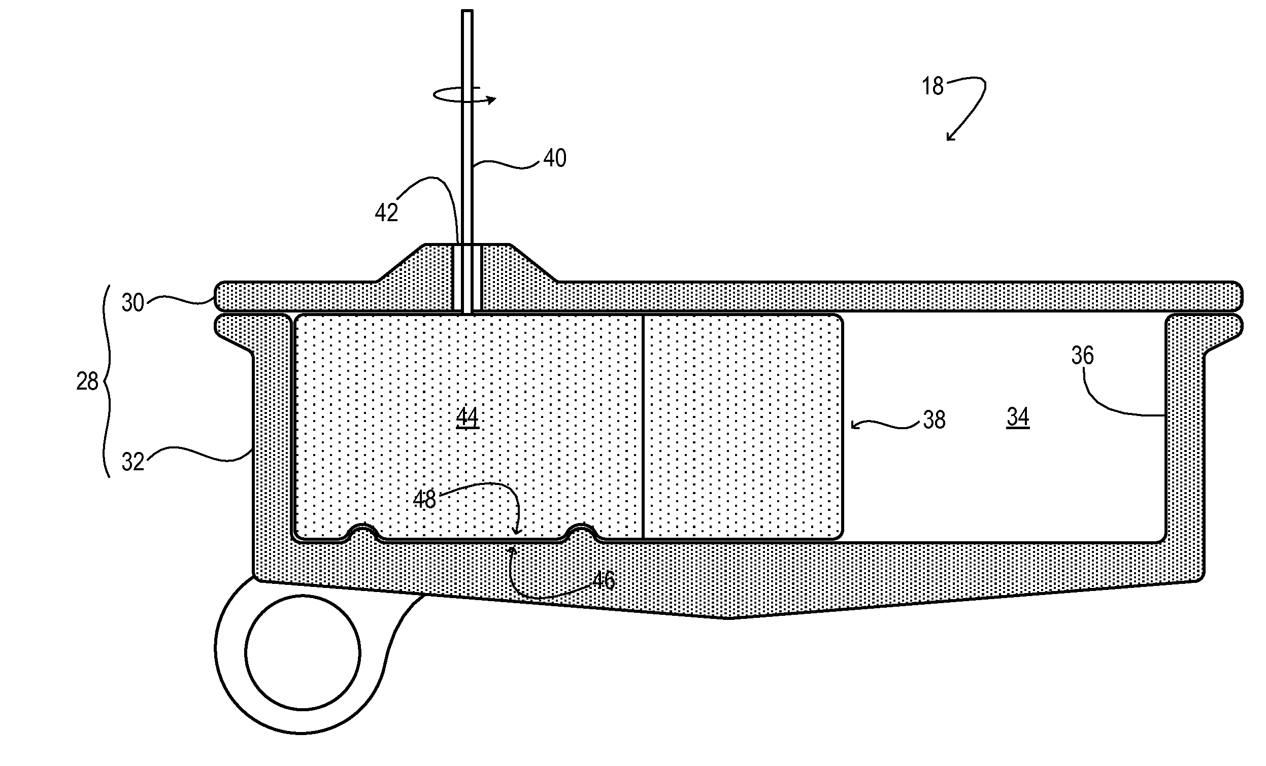
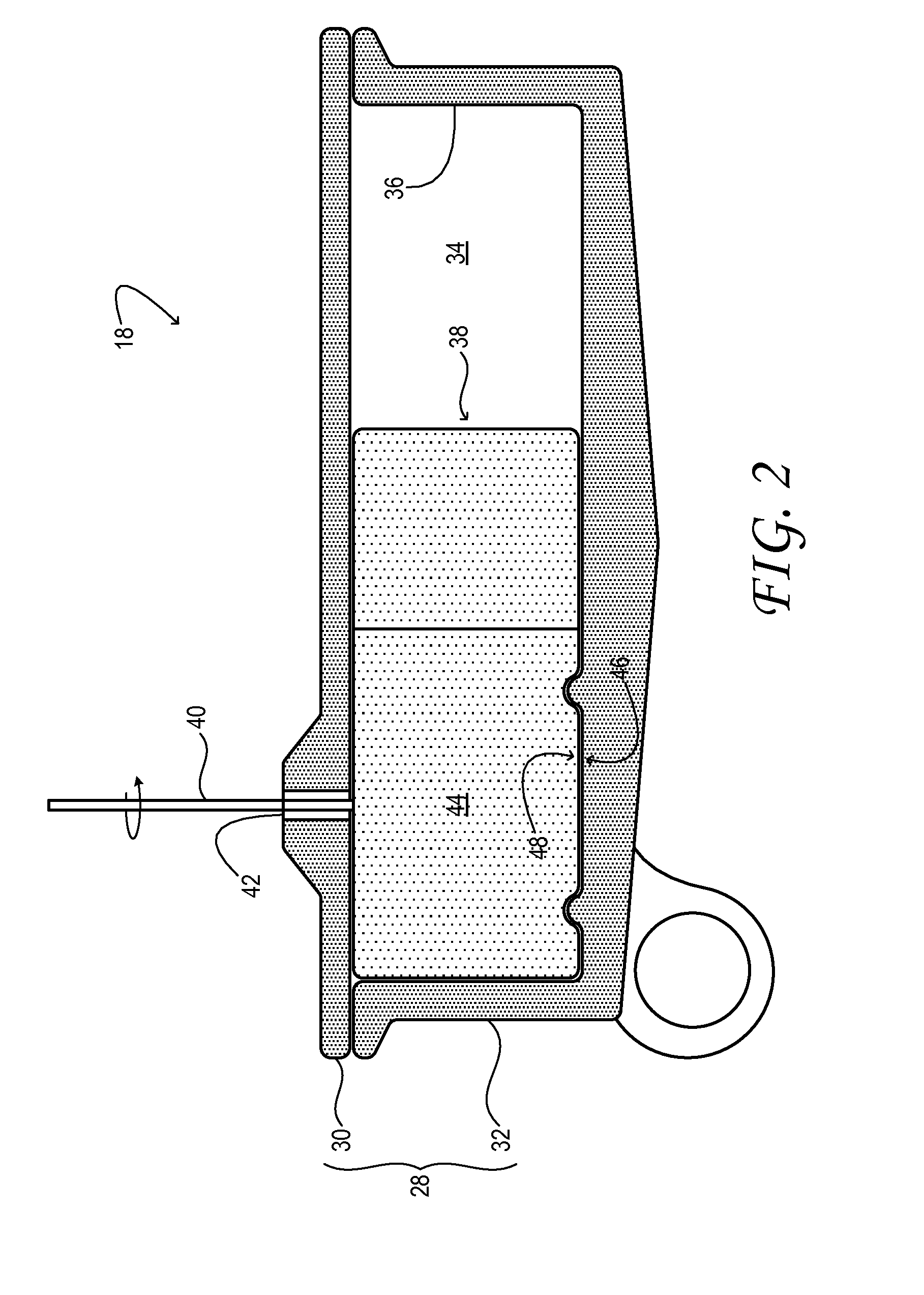
[0010]Aspects of this disclosure will now be described by example and with reference to the illustrated embodiments listed above. Components, process steps, and other elements that may be substantially the same in one or more embodiments are identified coordinately and are described with minimal repetition. It will be noted, however, that elements identified coordinately may also differ to some degree. The drawing figures included in this disclosure are schematic and generally not drawn to scale. Rather, the various drawing scales, aspect ratios, and numbers of components shown in the figures may be purposely distorted to make certain features or relationships easier to see.

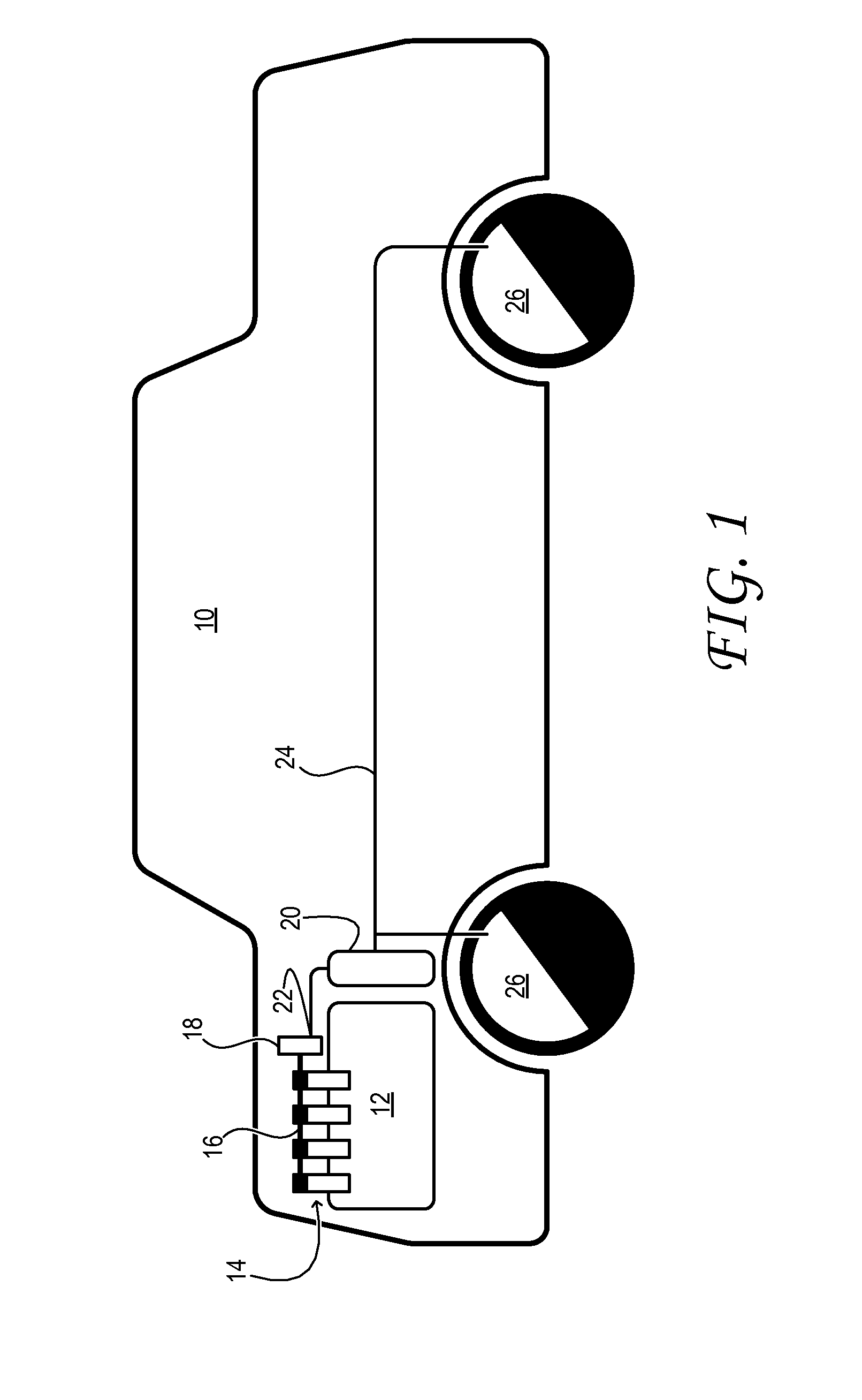
[0011]FIG. 1 schematically shows aspects of an example motor vehicle 10. The motor vehicle includes an engine 12, which provides motive force to drive the vehicle. The engine includes a plurality of valves 14—intake and / or exhaust valves, for example—mechanically actuated via camshaft 16. The camshaft may be driv...


PUM


Abstract

A rotary-vane vacuum pump comprises a stator and a vaned rotor, the stator partly defining an outlet chamber and including an outlet passage opening to the outlet chamber. The rotor is rotatably sealed to the stator; it has a sealing area to block the outlet passage, and, an unsealing area alignable with the outlet passage by rotation of the rotor to periodically unblock the outlet passage. The disclosed pump offers reduced resistance to lubricant oil discharge from the outlet passage, which results in lower differential pressure between inlet and outlet chambers at the end of the pumping cycle.

Description

TECHNICAL FIELD[0001]This application relates to the field of motor-vehicle engineering, and more particularly, to a vacuum pump for a motor-vehicle engine system.BACKGROUND AND SUMMARY[0002]A motor-vehicle engine system may include a vacuum pump to evacuate air from one or more motor-vehicle components. Such components may include a vacuum servo booster for hydraulic brakes, a throttle driver, or an actuated damper in the ventilation system of the vehicle, for example.[0003]The vacuum pump of a motor-vehicle engine system is typically a rotary-vane type positive-displacement pump. International Patent Publication Number WO2007 / 003215A1 shows one example of this type of pump. The pump includes a single-vane rotor that rotates within a stator and divides the interior volume of the stator into non-communicating chambers. Such chambers include an inlet chamber and an outlet chamber. The stator has an inlet passage that communicates with the inlet chamber, and an outlet passage that com...

Claims


Application Information

Patent Timeline
IPC IPC(8): F04C2/00
CPCF04C2/00F04C25/02F04C29/12F04C18/3441F04C2240/20
Inventor MOETAKEF, MOHAMMAD ALIPOE, STEVEZOUANI, ABDELKRIMCROWE, JONATHAN DENIS
Owner FORD GLOBAL TECH LLC
Why Eureka
Try Eureka