Electrochemical-based reactor for the removal of free cyanides and iron cyanide from industrial wastewater

a technology of electrochemical and industrial wastewater, which is applied in the direction of water/sludge/sewage treatment, water contaminants, sedimentation separation, etc., can solve the problems of reactor efficiency problems, decrease in concentration, and process efficiency decline over time, and achieve significant increase in iron consumption, high amount of ferrous ions, and increase in the volume of produced sludg

Inactive Publication Date: 2014-09-04
GHARIBI HAMED +1
View PDF6 Cites 13 Cited by
  • Summary
  • Abstract
  • Description
  • Claims
  • Application Information

AI Technical Summary

Benefits of technology

[0004]U.S. Pat. No. 3,816,275 [2] describes an electrolyzing process with iron plate as anode by which ferrocyanide and ferricyanide can be removed from waste liquor. These difficultly decomposable forms of cyanide make bound with the released iron ions which results in the formation of “Prussian Blue”, then surface as scum. The major drawback of this invention is that when the aim is removing all the forms of cyanide by just iron ions, the consumption of iron significantly increases, which in turn necessitates prompt replacement of the plates; besides, the volume of the produced sludge increases.
[0005]U.S. Pat. No. 4,312,760 [3] describes a method for removing cyanide (free or as a metal-complex) by adding ferrous bisulfite to the cyanide-contained wastewaters. This invention turns all the forms of cyanide as free cyanide and iron cyanide into the blue colloids of “Prussian Blue”, hence high amounts of ferrous ions are needed and also the produced sludge should be carefully disposed of. In addition, it is needed to add chemical compounds such as “ferrous bisulfite” to the wastewater, which is costly in terms of its price and the need for storage.
[0006]U. Bakir Ogutveren et al., [4] studied the feasibility of a bipolar trickle tower electrochemical reactor to remove cyanide from the effluent. In this study, they use Rasching rings as electrode. The results indicate that the reactor is able to effectively remove cyanide as fr...

Problems solved by technology

In fact, it is realistic that a process's efficiency decreases over time due to several problems, which in this case are sudden increase of cyanide concentration, corro...

Method used


Image

  • Electrochemical-based reactor for the removal of free cyanides and iron cyanide from industrial wastewater
  • Electrochemical-based reactor for the removal of free cyanides and iron cyanide from industrial wastewater
  • Electrochemical-based reactor for the removal of free cyanides and iron cyanide from industrial wastewater

Examples


example 1

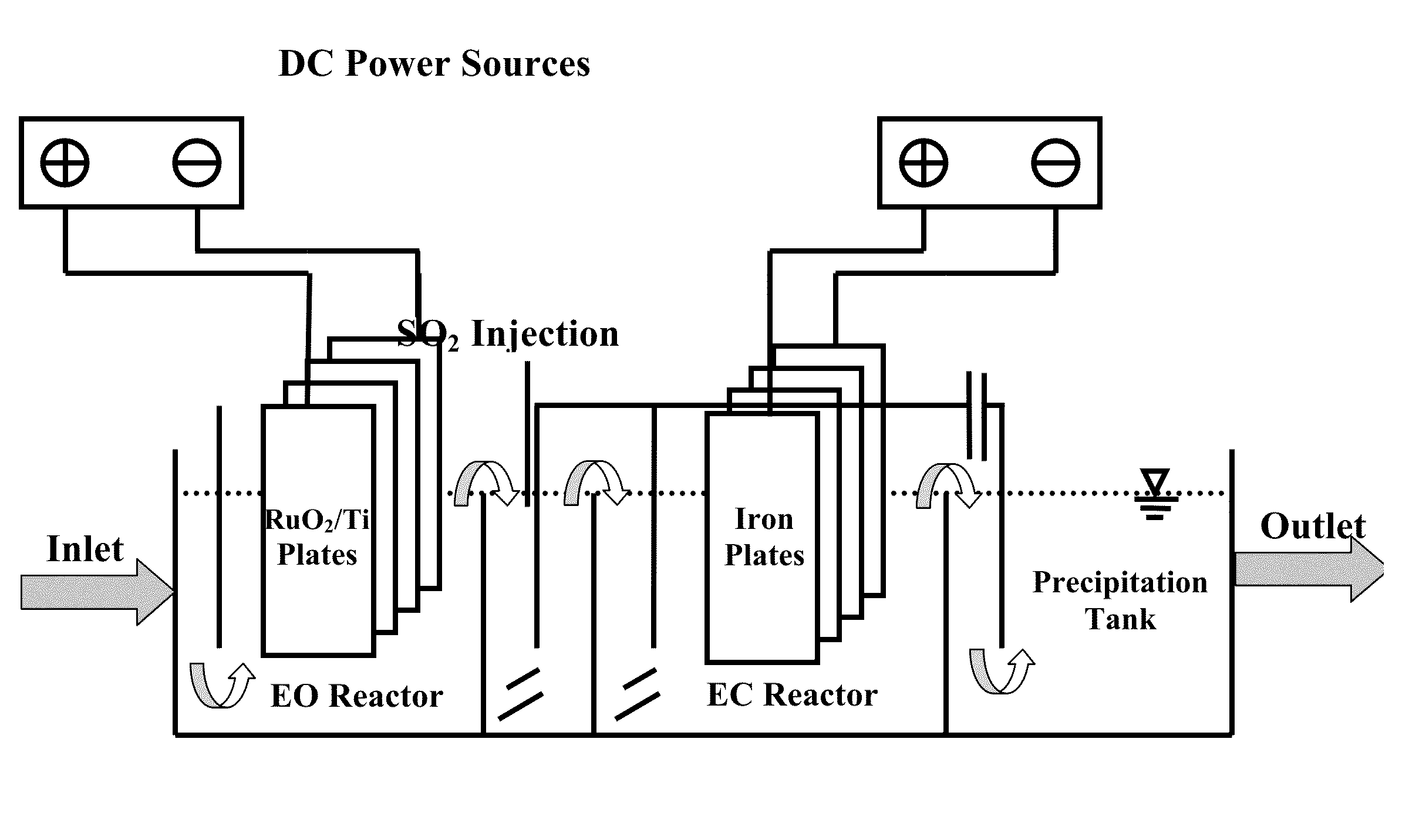
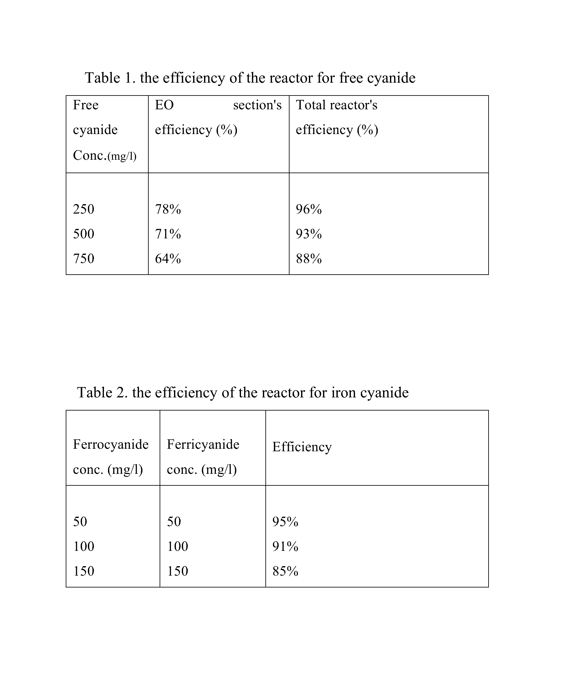
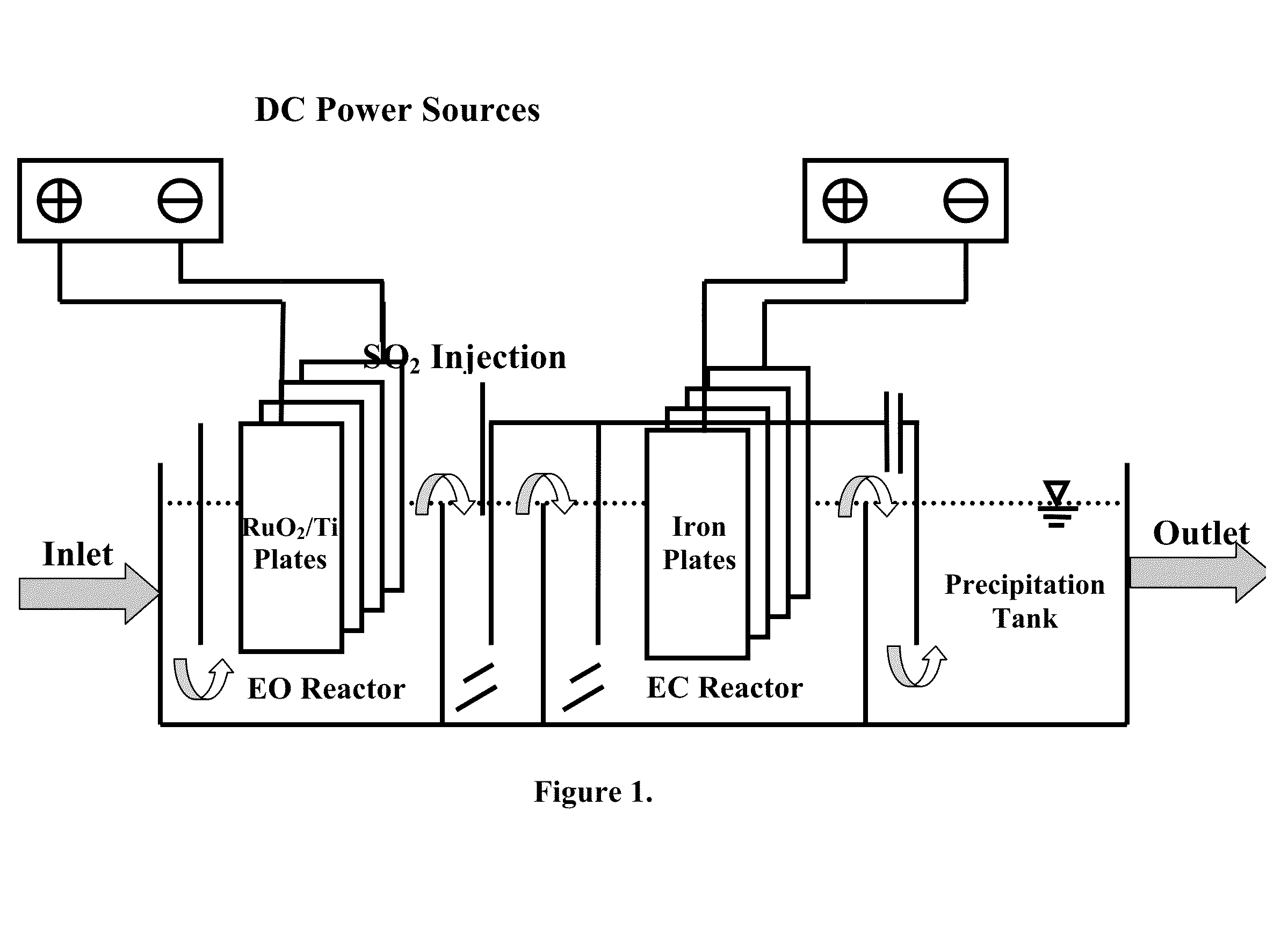
[0021]Three concentrations of free cyanide using NaCN and iron cyanide using potassium ferrocyanide and potassium ferricyanide are prepared. Besides, all tests are performed with having 800-1000 ppm chloride ions, due mainly to have actual concentration of this ion in the synthetic wastewater. The wastewater which its pH is adjusted to a pH >10 by using NaOH (preferably between 10 and 11) passes through the first section, i. e. electrooxidation, with the flow rate of 10.8 L / h and current density of 20 mA / cm2 at the anode surface. At the beginning of hydraulically mixing section, sulfur dioxide (SO2) was added to prepare an acidic (pH 3-6) and reductive condition. SO2 reacts with a variety of compounds in the bulk solution. The reaction of SO2 with residual chlorine (OCl−) is done more quickly. Afterwards, SO3−2 reacts with ferricyanide and transforms it to ferrocyanide. Therefore, every increase in the ferrocyanide / ferricyanide ratio is a good indicator for the complete decompositio...

example 2

[0023]In this example, the performance of the reactor is tested under non-ideal conditions in terms of chlorine or cyanide concentrations. The chlorine concentration in this run is 400-500 mg / l, and that of free cyanide is 1500 mg / l. The operational conditions and iron cyanide concentrations are the same as those in example 1. The efficiency of the reactor for free cyanide removal under these conditions is 52% and 87% for the electrooxidation part and total reactor, respectively. As the result indicates, the efficiency of the EO section decreases due to the lack of optimal conditions, but the efficiency of the total reactor proves that the other sections control these situations in terms of decreases of chloride ions and increases of free cyanide concentration.

example 3

[0024]In this example, the performance of the reactor was tested under conditions in which the concentration of ferrocyanide and ferricyanide suddenly increase in wastewater. In this case, the concentration of ferrocyanide and ferricyanide are both changed to 300 mg / l. The operational conditions for other parameters are the same as those in example 1. The efficiency of the EC section for ferrocyanide and ferricyanide removal decreased to 68%, as it was expected. It is due to this reason that the ferrocyanide and ferricyanide removal's efficiency is related to the release of iron from the iron plates in EC section. When the current density 15 mA / cm2, which was applied in example 1, was changed to 20 mA / cm2, the removal efficiency increased to 83%. Although the power consumption increases in such conditions, this test also shows that the reactor is able to control the sudden increase of iron cyanide concentrations.


PUM

PropertyMeasurementUnit
Current densityaaaaaaaaaa
Concentrationaaaaaaaaaa
Densityaaaaaaaaaa

Abstract

The present invention relates to a continuous bipolar electrochemically based reactor for the purpose of destroying free cyanide by direct and indirect oxidation and removing its strong complexes like ferrocyanide and ferricyanide by electrocoagulation. The designed reactor consists of four main sections, including electrooxidation, hydraulic mixing, electrocoagulation, and precipitation tank. The order of sections results in having a combination of reactions which separately remove cyanide and its compounds. The designed reactor shows a high flexibility in terms of handling highly variable kinds and concentrations of cyanide in the industrial wastewater effluents.

Description

FIELD OF THE INVENTION[0001]This invention relates to a continuous bipolar electrochemically based reactor for the purpose of destroying free cyanide by direct and indirect oxidation and removing its strong complexes like ferrocyanide and ferricyanide by electrocoagulation. The reactor consists of four main sections including electrooxidation, hydraulic mixing, electrocoagulation, and precipitation tank. In fact, the invention relates to a combination of reactions which separately remove cyanide and its compounds from industrial wastewater effluents; in the other words, the combination increases the flexibility of the reactor in terms of handling highly variable kinds and concentration of cyanide in the industrial wastewater effluents. Although cyanide removal by electrochemical technologies has been proposed by other researchers and inventors, the present invention relates to a combination of consequent reactions which their interrelationships enhance cyanide removal efficiency in ...

Claims


Application Information

Patent Timeline
IPC IPC(8): C02F1/463
CPCC02F1/463C02F1/4672C02F1/66C02F2001/46128C02F2001/46142C02F2101/18
Inventor GHARIBI, HAMEDMAHVI, AMIR HOSSEIN
Owner GHARIBI HAMED
Why Eureka
Try Eureka