Percutaneous mitral valve replacement and sealing

a technology of mitral valve and percutaneous mitral valve, applied in the field of valve replacement, can solve the problems of reducing cardiac output and increasing total stroke volum

Active Publication Date: 2014-09-11
CARDIOVALVE LTD
View PDF15 Cites 226 Cited by
  • Summary
  • Abstract
  • Description
  • Claims
  • Application Information

AI Technical Summary

Benefits of technology

[0014]For some applications, the prosthetic valve support is configured to be coupled to the native valve (e.g., to leaflets thereof) without eliminating the check valve functionality of the native valve, by allowing (1) the native leaflets to define a single orifice, and (2) the native valve to function as a single check valve (e.g., to function in a manner that is generally similar to the natural (e.g., physiological) function of the native valve). For some applications, the prosthetic valve support is configured to be coupled to the native valve (e.g., to leaflets thereof) without eliminating the check valve functionality by coupling together respective portions of two leaflets, such that (1) the native leaflets define two orifices, and (2) the native valve functions as two (e.g., parallel) check valves.
[0091]a second expandable prosthetic valve component, including a crimpable frame, and configured to be transcatheterally advanceable toward the native valve, placeable in the native valve while the second prosthetic valve component is in a crimped state thereof, and couplable to the first prosthetic valve component, expansion of the second prosthetic valve component facilitating coupling of the second prosthetic valve component to the first prosthetic valve component; and

Problems solved by technology

Regurgitation of blood from the ventricle into the atrium results in increased total stroke volume and decreased cardiac output, and ultimate weakening of the ventricle secondary to a volume overload and a pressure overload of the atrium.

Method used


Image

  • Percutaneous mitral valve replacement and sealing
  • Percutaneous mitral valve replacement and sealing
  • Percutaneous mitral valve replacement and sealing

Examples


Embodiment Construction

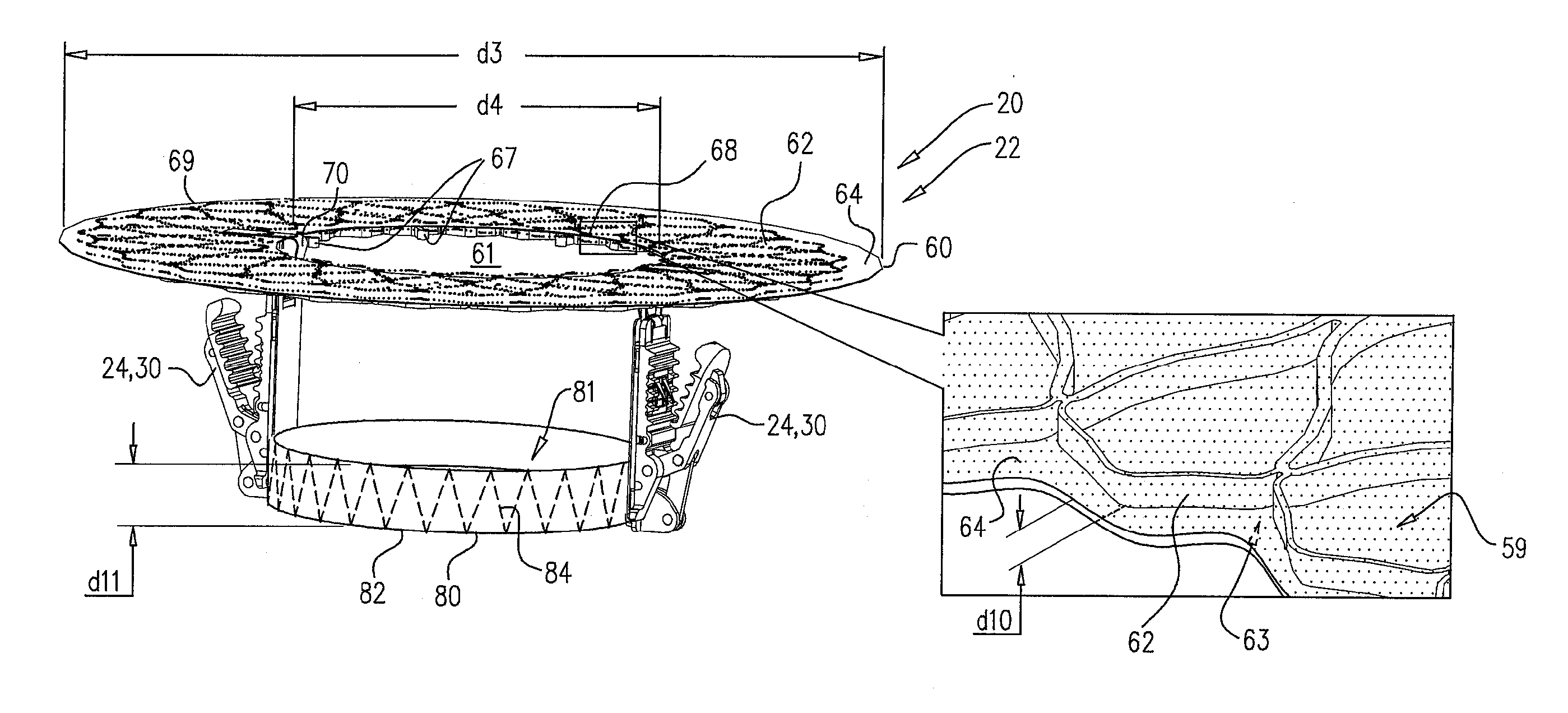
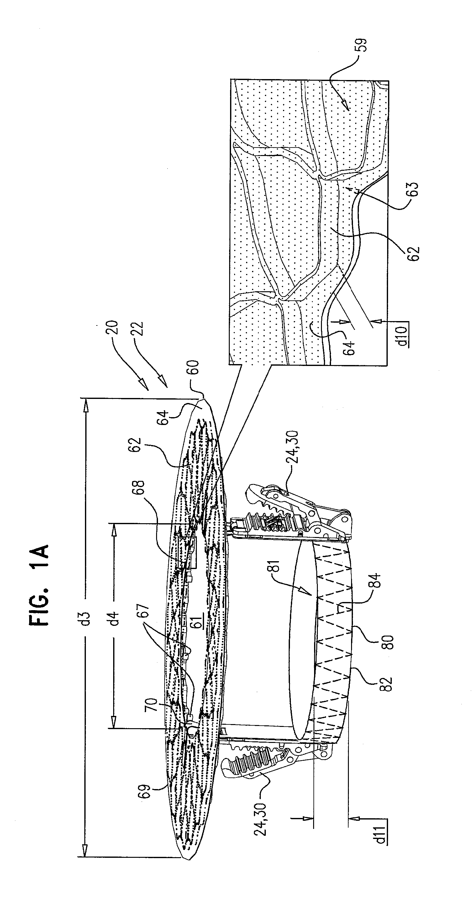
[0108]Reference is made to FIGS. 1A-D, which are schematic illustrations of apparatus 20, comprising a prosthetic valve support 22 for facilitating implantation of a prosthetic heart valve at a native heart valve of a subject, in accordance with some applications of the invention. Prosthetic valve support 22 comprises one or more tissue-engaging elements 24 (e.g., support-anchoring elements), and is typically configured to be coupled to the native heart valve (e.g., to leaflets thereof) without eliminating check valve functionality of the native heart valve (described in more detail hereinbelow). Typically, prosthetic valve 22 is configured to be transluminally, intracorporeally coupled to the native heart valve.

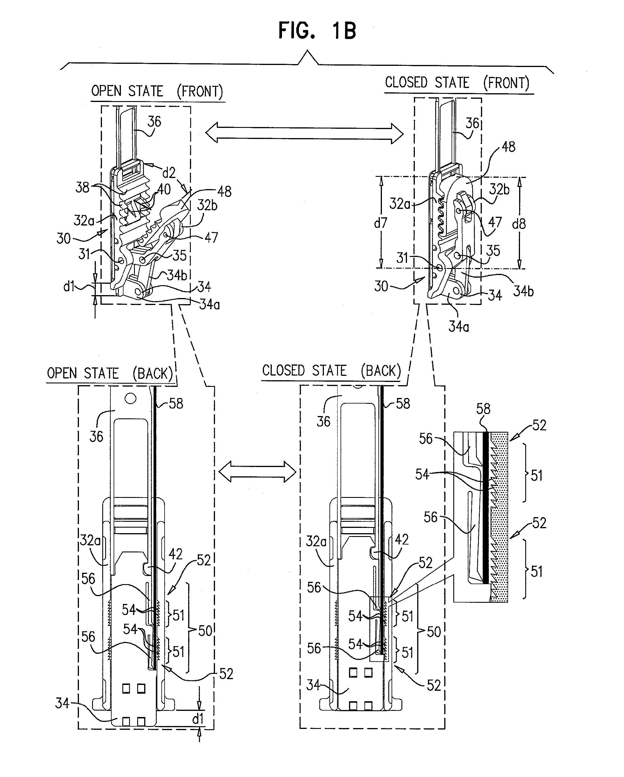
[0109]Typically, each tissue-engaging element 24 comprises a clip 30, which typically comprises a plurality of clip arms 32 (e.g., two clips arms, e.g., a first clip arm 32a and a second clip arm 32b), the clip being configured to be coupled to a leaflet of the native valve....


PUM


Abstract

Apparatus is provided for use with a prosthetic valve for implantation at a native valve of a subject, the native valve including at least one native leaflet, the apparatus including (1) a prosthetic valve support, including (a) an upstream support portion, being configured to be placed against an upstream side of the native valve, and having an inner perimeter that defines an opening that is configured to receive the prosthetic valve, and (b) at least one clip (i) comprising at least two clip arms and a clip-controller interface, the clip-controller interface being coupled to at least one of the clip arms, and (ii) being configured to be coupled to a native leaflet of the native valve; and (2) at least one clip controller, reversibly couplable to the clip-controller interface, and configured to facilitate opening and closing of the clip. Other embodiments are also described.

Description

CROSS-REFERENCES TO RELATED APPLICATIONS[0001]This application claims priority from:[0002]U.S. 61 / 515,372 to Gross, filed Aug. 5, 2011;[0003]U.S. 61 / 525,281 to Gross, filed Aug. 19, 2011;[0004]U.S. 61 / 537,276 to Gross, filed Sep. 21, 2011;[0005]U.S. 61 / 555,160 to Gross, filed Nov. 3, 2011;[0006]U.S. 61 / 588,892 to Gross, filed Jan. 20, 2012; and[0007]U.S. Ser. No. 13 / 412,814 to Gross, filed Mar. 6, 2012, all of which are incorporated herein by reference; and[0008]this application is a continuation-in-part of U.S. Ser. No. 13 / 412,814 to Gross, filed Mar. 6, 2012.[0009]This application is related to a PCT application to Gross, entitled, “Techniques for percutaneous mitral valve replacement and sealing,” filed on even date herewith.FIELD OF THE INVENTION[0010]Some applications of the present invention relate in general to valve replacement. More specifically, some applications of the present invention relate to prosthetic valves for replacement of a cardiac valve.BACKGROUND[0011]Ischemi...

Claims


Application Information

Patent Timeline
Patent Type & Authority Applications(United States)
IPC IPC(8): A61F2/24
CPCA61F2/2418A61F2250/006A61F2/2436A61F2/2409A61F2220/0025A61F2220/0091A61F2220/0016A61F2230/0013A61F2/2445A61F2230/0006A61F2/2427A61F2/2463A61F2210/0014A61F2220/0008A61F2/246A61B17/122A61B2017/00243A61F2/2442A61F2/2439A61F2/848A61F2250/0015A61F2250/0069A61F2250/0071A61F2/2454A61F2/2466
Inventor GROSSHACOHEN, GILMILLER, ERANZIPORY, YUVALREICH, TALKUTZIK, MEIRNEEMAN, ROTEM
Owner CARDIOVALVE LTD
Why Eureka
Try Eureka