
Interlocking cap and receptacle with detent feature and method and apparatus for separating interlocked cap and receptacle

a technology of interlocking cap and receptacle, which is applied in the field of system and apparatus for performing automated reagent-based biochemical assays, can solve the problems of reducing sample throughput and flexibility in assay choices, limited capabilities that complicate or inhibit multiple assay parallel processing, and most automated instruments suffer from limited set of assay capabilities, etc., to achieve accurate identification and/or access, increase thickness or radial geometry, and improve the effect of accuracy

Active Publication Date: 2014-09-18
GEN PROBE INC
View PDF0 Cites 41 Cited by
  • Summary
  • Abstract
  • Description
  • Claims
  • Application Information

AI Technical Summary

Benefits of technology

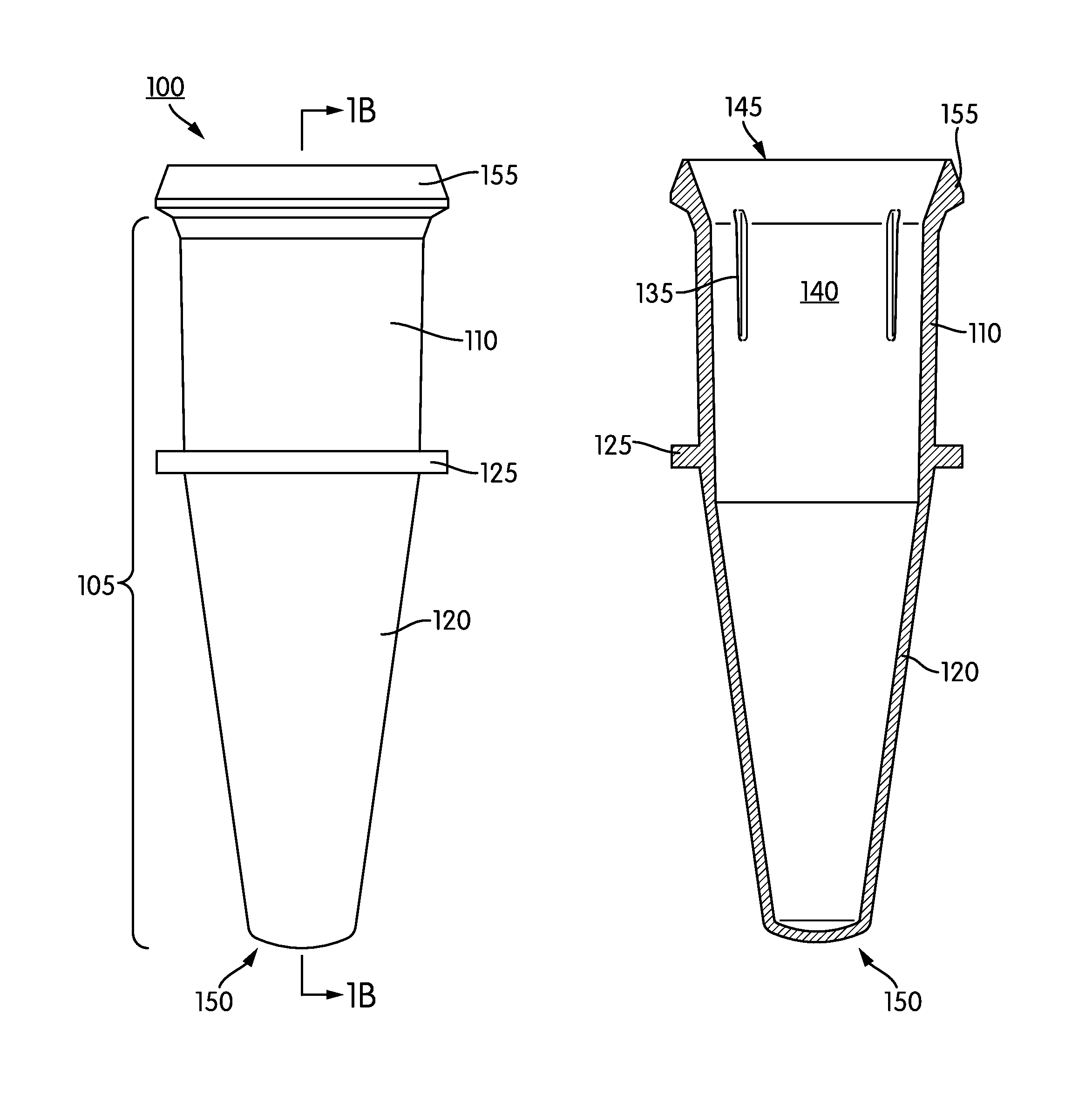
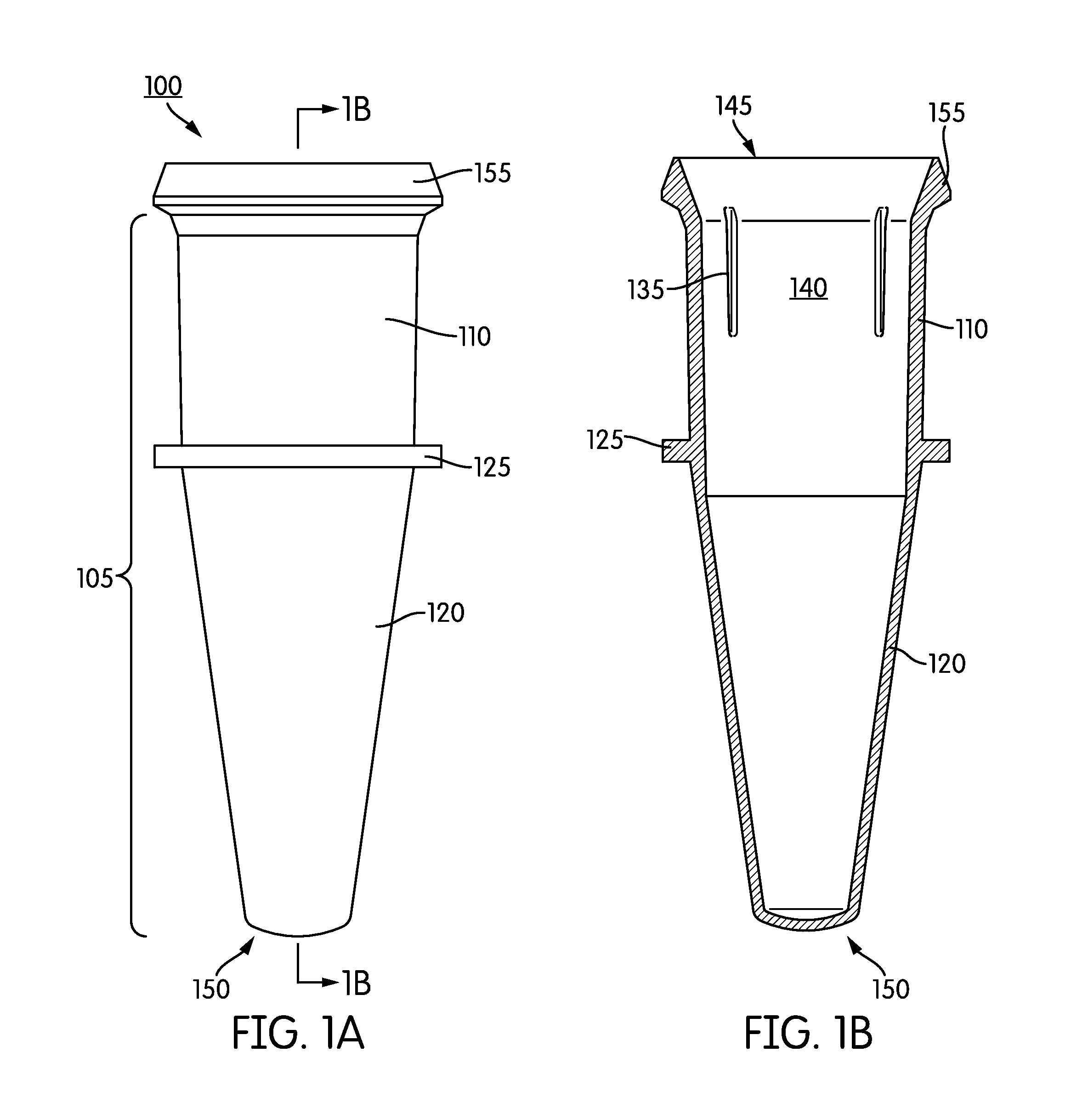
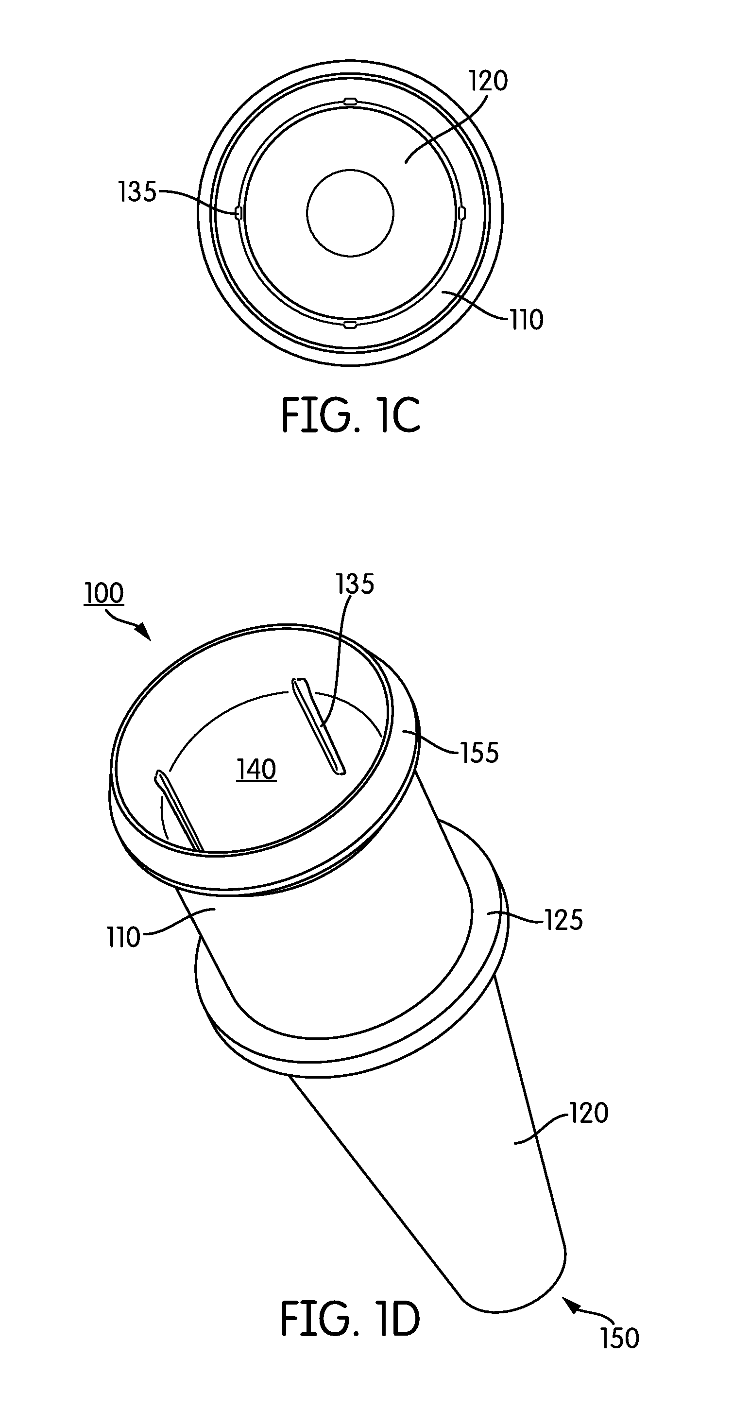
The present patent is about a system for performing automated biochemical assays using a single-piece receptacle and a cap. The receptacle has a cylindrical upper portion and a tapered lower portion with a lip at the open end. The upper portion has a longitudinally oriented groove on its inner surface. The cap has a lower portion with one or more annular rings for sealing engagement with the receptacle, an upper portion with a length and inner and outer surfaces, and one or more linear ribs on its inner surface that correspond to the grooves in the receptacle. The cap also has a lip with locking arms for securely engaging the lip of the receptacle. The system allows for automated removal of the cap from the receptacle. The technical effect of the invention is to provide a more efficient and automated system for performing biochemical assays.

Problems solved by technology

Automated molecular assay instrumentation offers numerous advantages, however most automated instruments suffer from a limited set of assay capabilities.
These limited capabilities complicate or inhibit parallel processing of multiple assays and, as a result, reduce sample throughput and flexibility in assay choices.
No document, however, is admitted to be prior art to the claimed subject matter.

Method used


Image

  • Interlocking cap and receptacle with detent feature and method and apparatus for separating interlocked cap and receptacle
  • Interlocking cap and receptacle with detent feature and method and apparatus for separating interlocked cap and receptacle
  • Interlocking cap and receptacle with detent feature and method and apparatus for separating interlocked cap and receptacle

Examples


Embodiment Construction

[0038]The present disclosure relates to a system, apparatus, and method for automated processing of a sample receptacle holder that is adapted for use in an automated instrument capable of performing nucleic acid-based amplification assays. Also provided are methods for conducting automated, random-access temperature cycling processes using the same.

[0039]Before the present systems, methods, and apparatuses are described, it is to be understood that this disclosure is not limited to particular methods and experimental conditions described, as such methods and conditions may vary. It is also to be understood that the terminology used herein is for purposes of describing particular embodiments only, and is not intended to be limiting, since the scope of the present disclosure will be limited only in the appended claims.

[0040]As used in this specification and the appended claims, the singular forms “a,”“an,” and “the” include plural references unless the context clearly dictates otherw...


PUM

PropertyMeasurementUnit
Structureaaaaaaaaaa
Lengthaaaaaaaaaa
Shapeaaaaaaaaaa

Abstract

System, apparatuses, and methods for performing automated reagent-based analysis are provided. Also provided are methods for automated attachment of a cap to a reaction receptacle, and automated removal of a cap from a capped reaction receptacle.

Description

CROSS REFERENCE TO RELATED APPLICATION[0001]This application claims the benefit under 35 U.S.C. §119(e) of the filing date of U.S. Provisional Application No. 61 / 782,320, filed Mar. 14, 2013, which is incorporated herein by reference.BACKGROUND FIELD[0002]The present disclosure relates to systems and apparatuses for performing automated reagent-based biochemical assays.BACKGROUND INFORMATION[0003]Automated molecular assay instrumentation offers numerous advantages, however most automated instruments suffer from a limited set of assay capabilities. These limited capabilities complicate or inhibit parallel processing of multiple assays and, as a result, reduce sample throughput and flexibility in assay choices. This is particularly true for sensitive assays such as those involving nucleic acid detection and / or an amplification procedure. There are many procedures in use for amplifying nucleic acids, including the polymerase chain reaction (PCR), (see, e.g., Mullis, “Process for Amplif...

Claims


Application Information

Patent Timeline
IPC IPC(8): B01L3/00B65B69/00
CPCB01L3/50825B01L2300/0838B01L3/502B01L3/52G01N2035/0436B01L3/50853B01L3/523B65D39/0017B01L3/527G01N35/026C12Q1/686B01L3/5082B67B7/16B01L2300/042B01L2300/044B01L2300/046G01N2035/0405B01L3/5085B01L2200/16B01L2300/0609B01L2300/0829B65B69/00B01L3/50855B01L2200/026B01L2200/0668B01L2200/0689B01L2400/0406Y10T436/11B65D17/50G01N30/6091B01L2300/047B01L2300/048G01N35/10B01L2200/142G01N35/1002G01N2035/00287G01N35/1079B01L2200/025B65D1/0207B65D1/34B65D39/0029B65D2539/003B01L2300/0851B01L2300/0858B01L2200/02B01L2300/0832B01L2300/12B01L2200/141B65D1/36G01N35/0099
Inventor KNIGHT, BYRON J.
Owner GEN PROBE INC
Learn More