Hybrid metal fiber flywheel

a metal fiber and flywheel technology, applied in the field of flywheels, can solve the problems of increasing the speed of the flywheel and ultimately reaching the physical speed limit, failure to explodely release all its stored energy instantaneously, and reducing the functional capability of the assembled flywheel. , to achieve the effect of increasing the structural capability and increasing the functional capability of the assembled flywheel

Inactive Publication Date: 2014-09-18
SIMONS GERALD FR
View PDF5 Cites 2 Cited by
  • Summary
  • Abstract
  • Description
  • Claims
  • Application Information

AI Technical Summary

Benefits of technology

[0004]The embodiment of the present invention is a flywheel or alternatively called a momentum wheel, assembled of structural component parts so juxtaposed as to increase the structural capability of each of the individual component thus increasing the functional capability of the assembled flywheel.BACKGROUND OF THE INVENTION
[0007]The flywheel of the present invention is an assembly of primarily dense materials and as such stores a large amount of energy at a rotational speed that does not benefit greatly from the use of a hard vacuum and allows the use of conventional bearings, thus avoiding the complications of the abnormally sophisticated bearings.
[0010]Metal flywheels of prior art are typically made by a forging process and then finish machined to detail the various thickness configurations of the specifically designed wheel. In order to maximize its functional performance and minimize its stresses the wheel is designed with a thicker hub, then a thinner section extending from the hub to a thickened rim. Each flywheel undergoes large non recurring engineering and tooling costs. The flywheel of the present invention provides for extreme flexibility of application since it is simply an assembly of high density material such as steel that is rolled to a flat dimension, cut to a circular shape using conventional cutting tools, bonded to laminations of less dense material using existing processes. Its functional capacity is determined by the number of laminations and the radius of their circular shape. The rolling process done at the steel mill is effectively a forging process. Being of such simple construction allows the configuration of the flywheel to easily be built to accommodate whatever functional requirement exists.

Problems solved by technology

As technology improved the speed of the flywheels was increased and ultimately reached a physical speed limit due to stresses caused by the rotational speed.
When the rotational speed reaches a limit at which the stresses exceed the capability of the rotating material, it fails explosively releasing all its stored energy instantaneously.
The function of a flywheel depends upon the mass of the rotating body and unfortunately those fibers are light in mass and therefore little storage was obtained.
Running a rotating body at those speed involved enormous physical problems in bearings, aerodynamic drag losses and aerodynamic heating as well since the tip speeds were supersonic.
A rotor failure was of even greater concern.
The sudden release of energy stored in the wheel was explosive and potentially could cause enormous damage.
Containment housings were developed that are unreasonably heavy and expensive.
Hard vacuums are virtually impossible to continuously maintain as the wheel ages.
The speed of flywheels used as rotating bodies in gyroscopes, since it is impractical to bury them in underground or equivalent bunkers, were limited to slower speeds resulting in large safety factors or sizes that an explosive failure could be contained.
That limitation has restricted the use in applications that benefit from the use of large gyroscopes.
Random failures occur, and in prior art, when a failure occurs all the stored energy was instantaneously released.
In some cases, layers of wound fiber were bonded into a pseudo laminations but a failure of a fiber would cause the entire mass to disintegrate.
Ultimately with fatigue and temperature and stress cycling, an unbalance might be detected and the use of the flywheel terminated.
Each flywheel undergoes large non recurring engineering and tooling costs.

Method used


Image

  • Hybrid metal fiber flywheel
  • Hybrid metal fiber flywheel
  • Hybrid metal fiber flywheel

Examples


Embodiment Construction

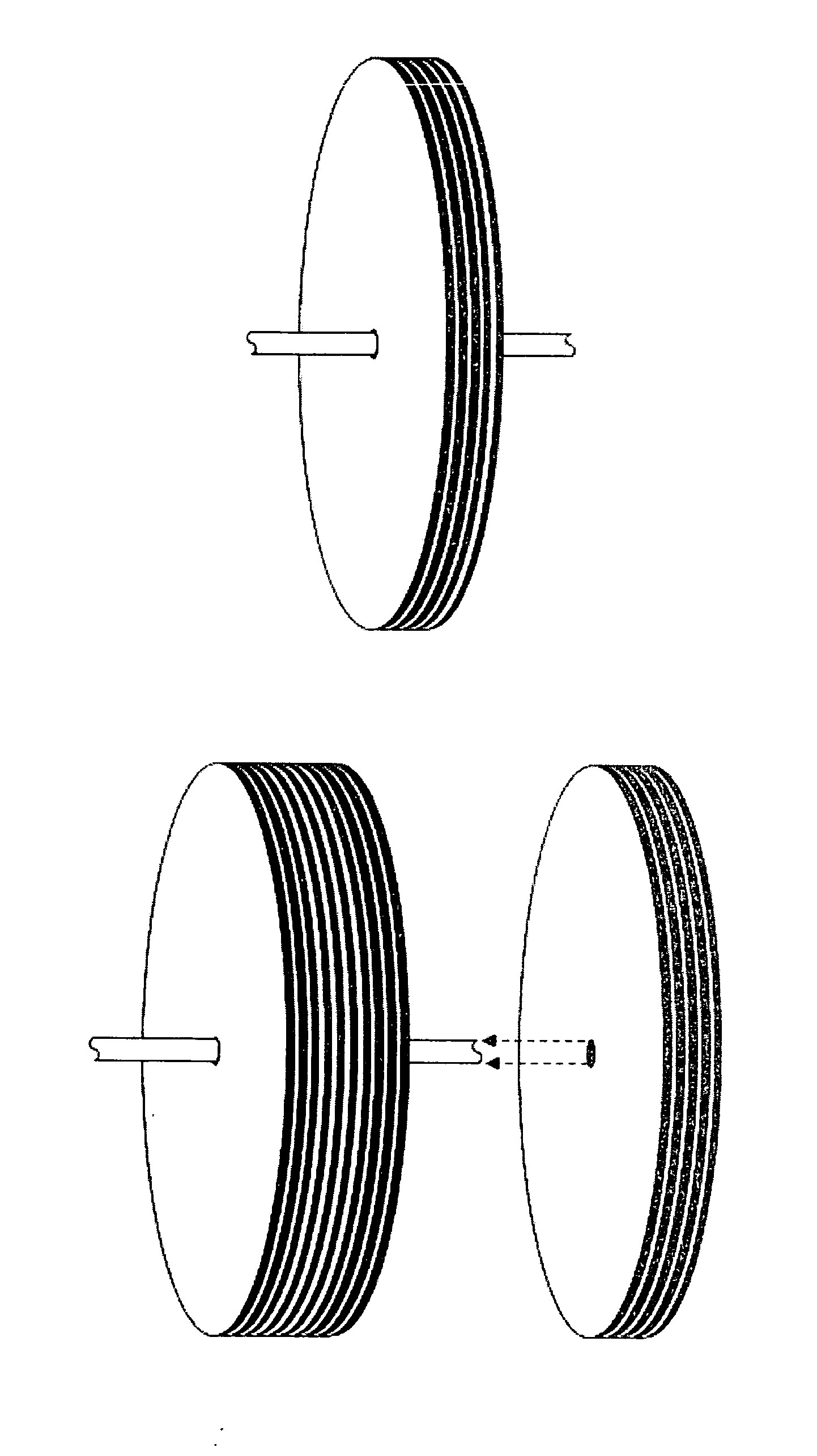
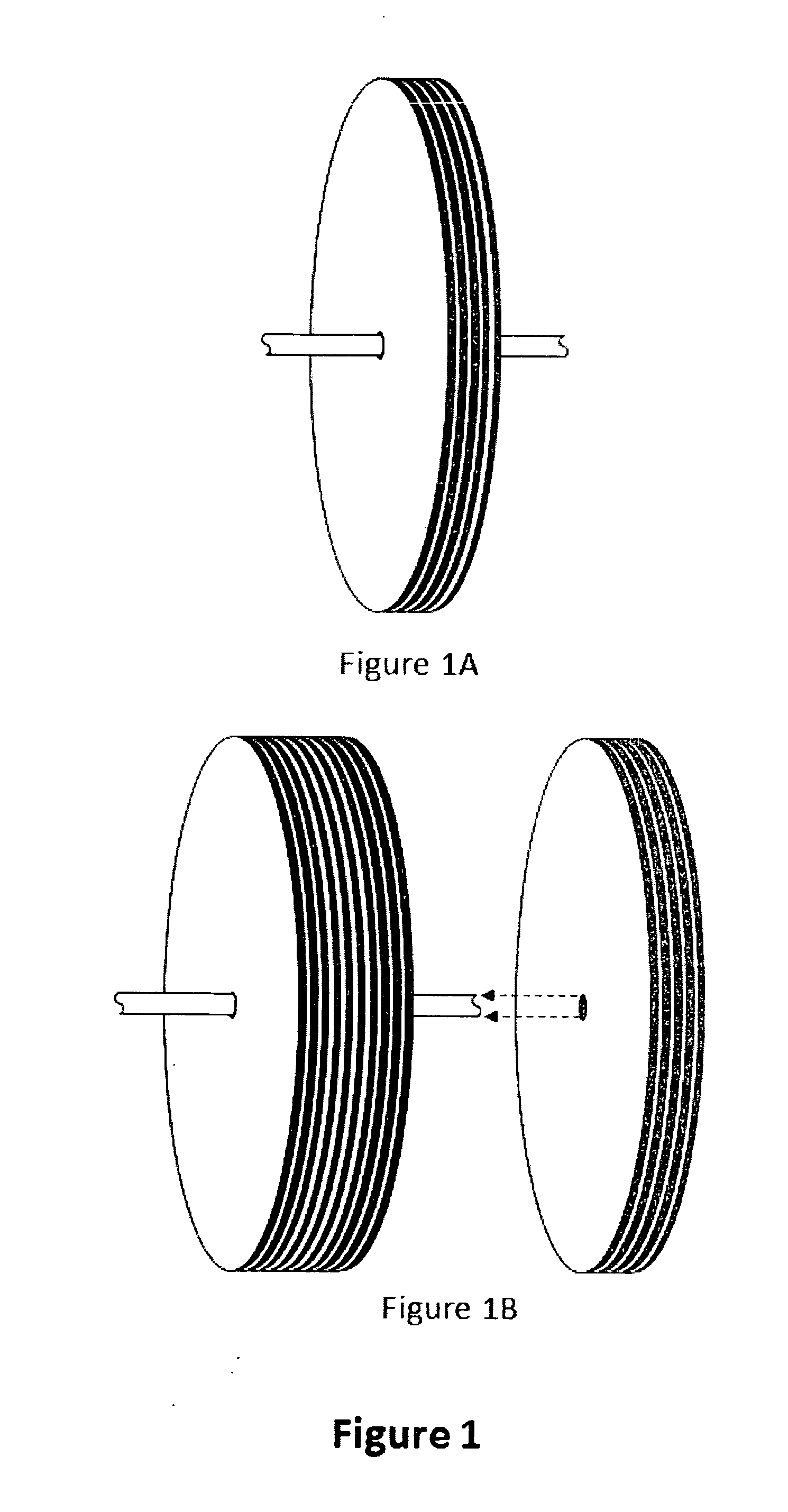
[0030]FIG. 1a shows a laminated fiber wrapped flywheel module mounted on a shaft. FIG. 1b shows two of the same laminated fiber wrapped flywheel modules mounted on the same shaft with a third module ready to be mounted on the same shaft. Each module, when mounted on the shaft is a complete flywheel and contains a given amount of stored energy. Its functional characteristics are established by its radius and the mass that results from the number of laminations. By adding modules to a common shaft the functional capability of the total flywheel assembly may be increased in increments to meet the design objective. Moreover mounting space may be an issue and to accommodate such limitation the radius of the module may be altered as necessary to fit the available space. The modular assembly with the ability to select the desired radius provides enormous application flexibility.

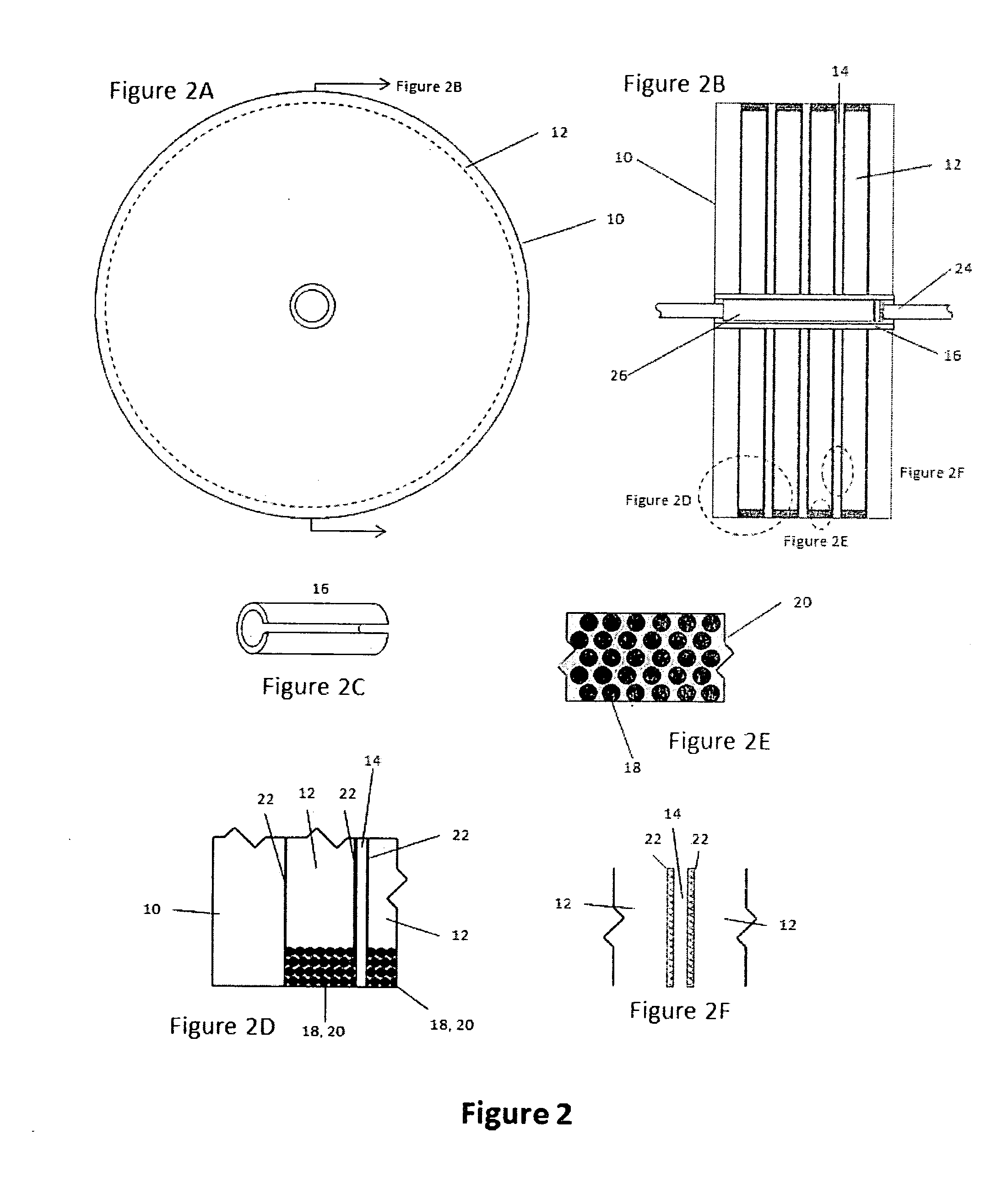
[0031]The flywheel module is an assembly using alternate circular laminations of different density materials bond...


PUM


Abstract

An energy storage flywheel whose energy storage capacity has been enhanced by the use of circumferentially applied composite fibers. The use of high density metal wafers being laminated with isolating low density laminations ensures maximum energy storage for a given mass and safely limits instant total energy release or the ejection of failed objects upon the event of a mechanical failure.

Description

CROSS REFERENCE TO RELATED APPLICATIONS[0001]This application claims the benefit of Provisional Patent Application No. 61 / 852,000STATEMENT REGARDING FEDERALLY SPONSORED RESEARCH AND DEVELOPMENT[0002]Not applicableBACKGROUND OF THE INVENTIONField of the Invention (Technical Field)[0003]The present invention relates to flywheels, utilizing the mass benefits of metal, the high strength bonding capability of flexible epoxies and the structural benefits of high strength carbon composites.BRIEF SUMMARY OF THE INVENTION[0004]The embodiment of the present invention is a flywheel or alternatively called a momentum wheel, assembled of structural component parts so juxtaposed as to increase the structural capability of each of the individual component thus increasing the functional capability of the assembled flywheel.BACKGROUND OF THE INVENTION[0005]The energy storage capability and angular momentum of flywheels has long been recognized as a practical and efficient means to store energy and, ...

Claims


Application Information

Patent Timeline
Patent Type & Authority Applications(United States)
IPC IPC(8): H02K7/02
CPCH02K7/025Y02E60/16F16F15/30F16F15/305Y10T74/212
Inventor SIMONS, GERALD FRANK
Owner SIMONS GERALD FR
Why Eureka
Try Eureka