Furnance employing components for use with graphite hot zone

Inactive Publication Date: 2014-09-18
ADVANCED RENEWABLEENERGY COMPANY
View PDF9 Cites 6 Cited by
  • Summary
  • Abstract
  • Description
  • Claims
  • Application Information

AI Technical Summary

Benefits of technology

[0016]The present invention additionally relates to a method of growing a sapphire crystal in a furnace which comprises a furnace housing; a hot zone which comprises insulation and at least one heater both accommodated within the furnace housing; a crucible located within the hot zone and the crucible having an opening; and at least one of a crucible enclosure, which is impermeable to at least carbon, covering at least the opening of the crucible and at least a portion of a side

Problems solved by technology

Graphite hot zones are relatively inexpensive—compared to refractory metal hot zones—and also provide excellent insulation, but contamination of the melt, contained within the crucible during the crystal growing process, is a great concern.
More specifically, any contamination, e.g., carbon atoms or other molecules which separate from either the graphite heating element and/or the graphite insulating element

Method used


Image

  • Furnance employing components for use with graphite hot zone
  • Furnance employing components for use with graphite hot zone
  • Furnance employing components for use with graphite hot zone

Examples


second embodiment

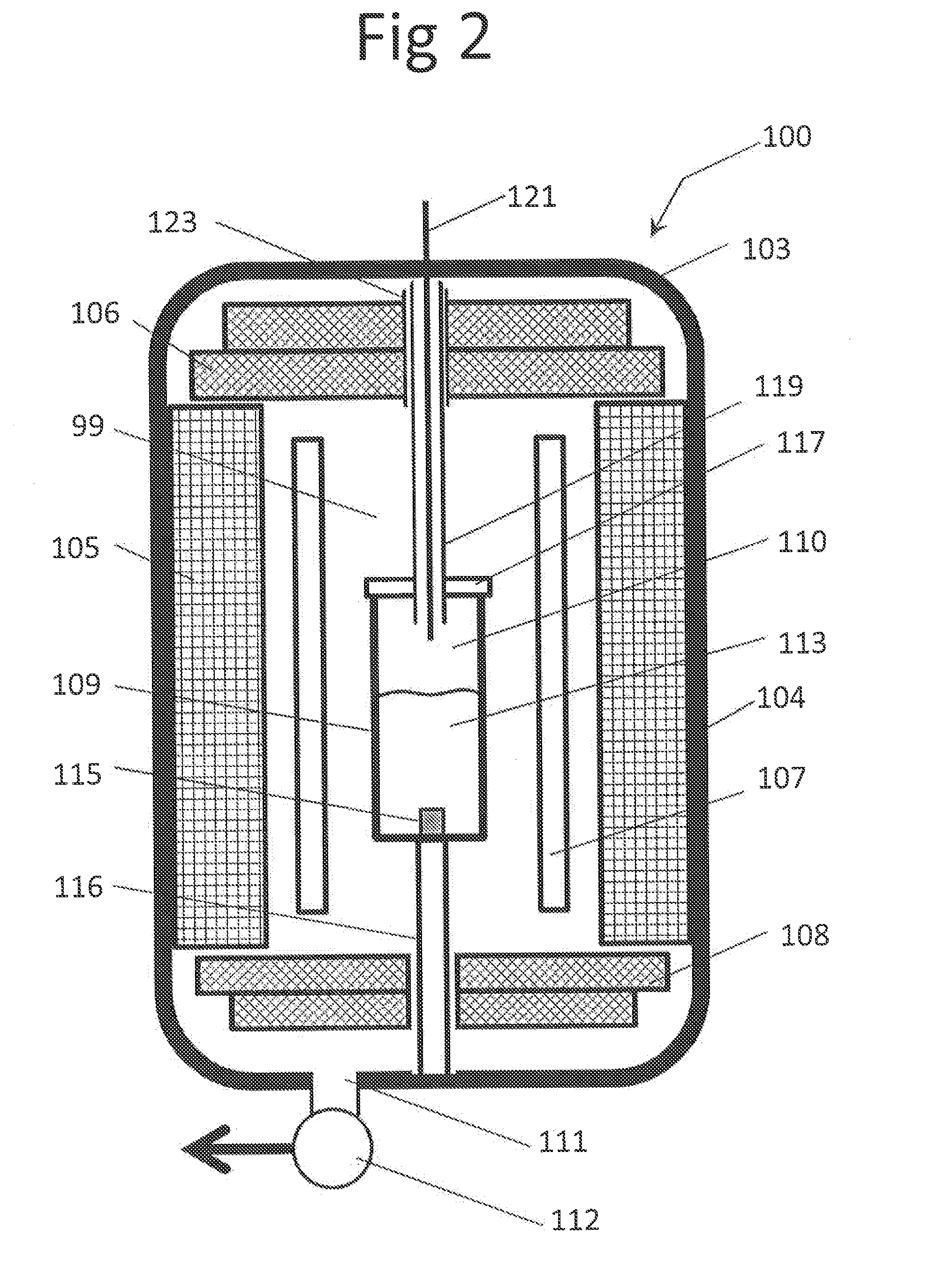
[0035]With reference now to FIG. 2, the present invention will now be described. It is to be appreciated that this configuration of the furnace 100 is similar to the embodiment shown in FIG. 1 except that, according to this embodiment, a first (crucible lid) conduit 119 extends from the crucible lid 117 to and through the hole 123 formed in the top shield insulation 106. As a result of this arrangement, the first conduit 119 passes through hole 123 so that the instrumentation 121, such as probe rod, may pass through and along the first conduit 119 and directly communicate and access the melt 113 contained within the interior chamber 110 of the crucible 109 without communicating or interacting with the interior compartment 99 of the furnace 100. That is, the first conduit 119 completely physically shields the probe rod 121 from exposure to any carbonaceous contaminants or other undesired constituents or contaminants, from either the insulation 105 and / or the heater 107, which are con...

third embodiment

[0038]With reference now to FIG. 3, the present invention will now be described. It is to be appreciated that this configuration of the furnace 100 is similar to the embodiment shown in FIG. 2 except that, according to this embodiment, the first (crucible lid) conduit 119 extends completely through and projects out from the furnace housing 103 and thus directly communicates with an external environment surrounding the furnace 100. According to this embodiment, an inert gas source S is connected to an inlet of the first conduit 119 for supplying a desired inert purge gas (e.g., such as argon or helium, for example) thereto. The inert purge gas is conveyed along the length of the first conduit 119 into the interior chamber 110 of the crucible 109 and utilized to create a slight positive pressure within the interior chamber 110 of the crucible 109. The inventors have found that higher furnace pressures (e.g., pressures above 10 Torr, for example) during the melting of the charge materi...

fourth embodiment

[0041]With reference now to FIG. 4, the present invention will now be described. It is to be appreciated that this configuration of the furnace is similar to the embodiment shown in FIG. 3 except the crucible lid includes both a centrally located first conduit 119 and a concentric outer second conduit 120 which completely surrounds the first conduit 119. The first and the second conduits 119, 120 both extend from the hole 123, formed in the top shield insulation 106, to the central opening formed in the crucible lid 117. Although the first conduit 119 is shown enclosed and surrounded by the second conduit 120, it is to be appreciated that alternative configurations of the two conduits can be employed without departing from the spirit and scope of the present invention.

[0042]According to this embodiment, an inert gas source S is typically connected and communicates with a first inlet of the first conduit 119 which projects and extends from a top exterior surface of the furnace housin...


PUM


Abstract

A furnace for growing sapphire crystal in which the furnace comprises a furnace housing; a hot zone which comprises insulation and a heater which are both accommodated within the furnace housing; a crucible located within the hot zone and the crucible has an opening. Either a crucible lid covers the opening of the crucible, and the crucible lid has a first conduit which extends therefrom or a crucible enclosure surrounds at least a side wall and a top portion of the crucible and the crucible enclosure is impermeable to at least carbon preventing carbon contamination of a melt contained within the crucible.

Description

[0001]This application claims the benefit of U.S. provisional application No. 61 / 779,409 filed Mar. 13, 2013.FIELD OF THE INVENTION[0002]The present invention generally relates to crystal growth furnaces and hot zones and, more particularly, relates to providing a barrier formed between the crucible and the hot zone of the furnace, which is impermeable to graphite / carbon or any other undesired components and / or constituents, so as to prevent contamination of the sapphire crystal during crystal growth process.BACKGROUND OF THE INVENTION[0003]Hot zones are components in high-temperature furnaces used for various applications, including the growth of crystals such as sapphire, silicon, and other similar materials. During crystal growth process, a hot zone typically includes at least one heating element and at least one insulating element surrounding the heating element. A charge material, located within a crucible, is melted within the hot zone and then gradually allowed to cool within...

Claims


Application Information

Patent Timeline
IPC IPC(8): C30B11/00
CPCC30B11/002Y10T117/1092C30B29/20
Inventor WENDEL, THOMAS DEWAYNEKLOTZ, MATTHEW GARYKENT, DAVID MSERPA, NICHOLAS JOSEPHKHATTAK, CHANDRA PULLAL, SAURABH
Owner ADVANCED RENEWABLEENERGY COMPANY
Why Eureka
Try Eureka