Electric linear motion actuator and electric brake system

a technology of electric brake system and actuator, which is applied in the direction of instruments, static/dynamic balance measurement, gearing, etc., can solve the problem of extremely limited time during which this special procedure can be performed

Active Publication Date: 2014-09-18
NTN CORP
View PDF7 Cites 17 Cited by
  • Summary
  • Abstract
  • Description
  • Claims
  • Application Information

AI Technical Summary

Benefits of technology

[0022]By using this electric linear motion actuator, it is possible to set the clearance to a predetermined value by controlling the electric motor to rotate the electric motor by the target rotational angle which is calculated based on the magnitude of the load detected by the load sensor, when pressure on the object is released. By using this electric linear motion actuator in an electric brake system, it is possible to adjust the clearance when the brake is released during normal braking operation.

Problems solved by technology

But in a vehicle brake system, the time during which this special procedure can be performed is extremely limited.

Method used


Image

  • Electric linear motion actuator and electric brake system
  • Electric linear motion actuator and electric brake system
  • Electric linear motion actuator and electric brake system

Examples


Embodiment Construction

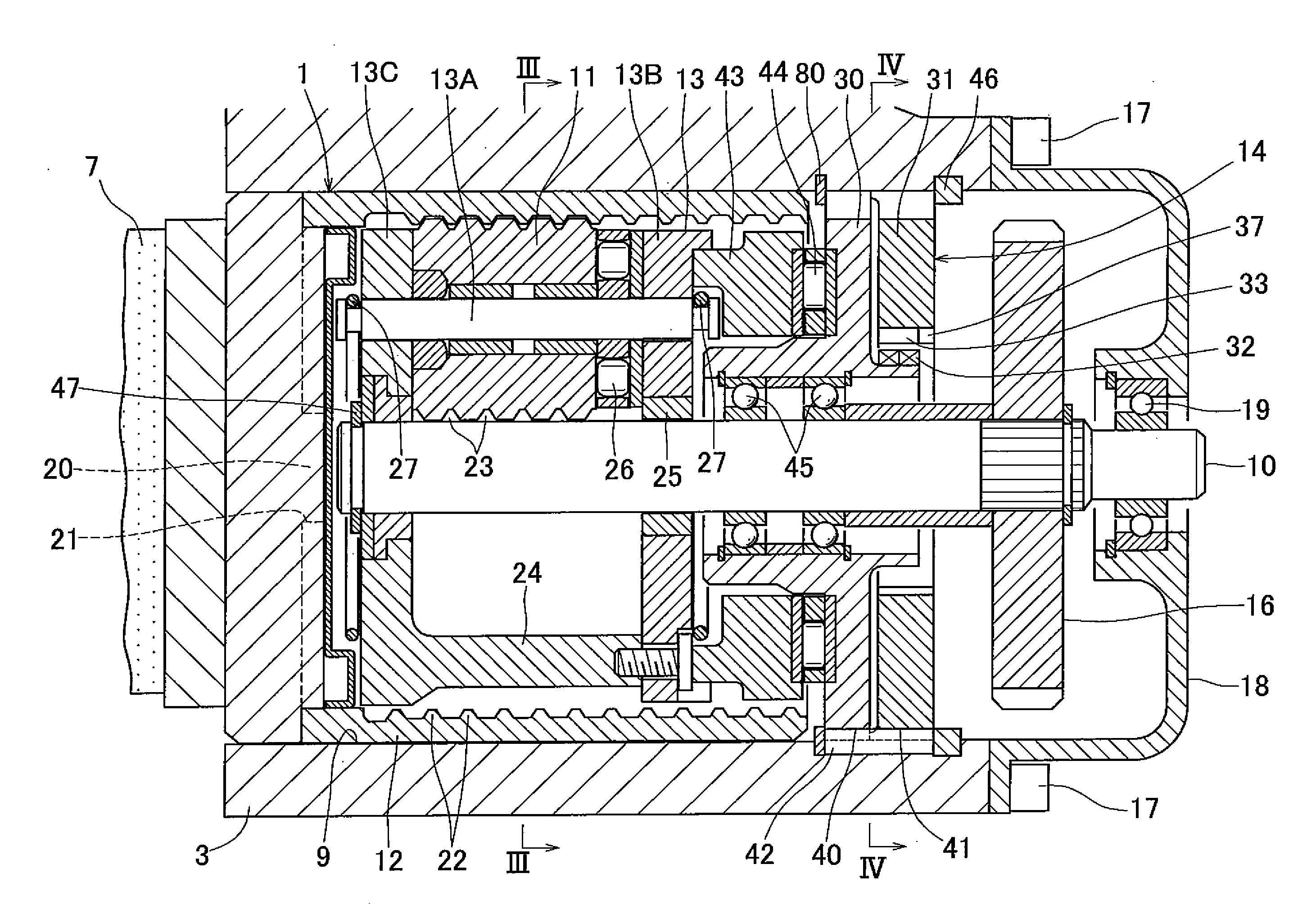
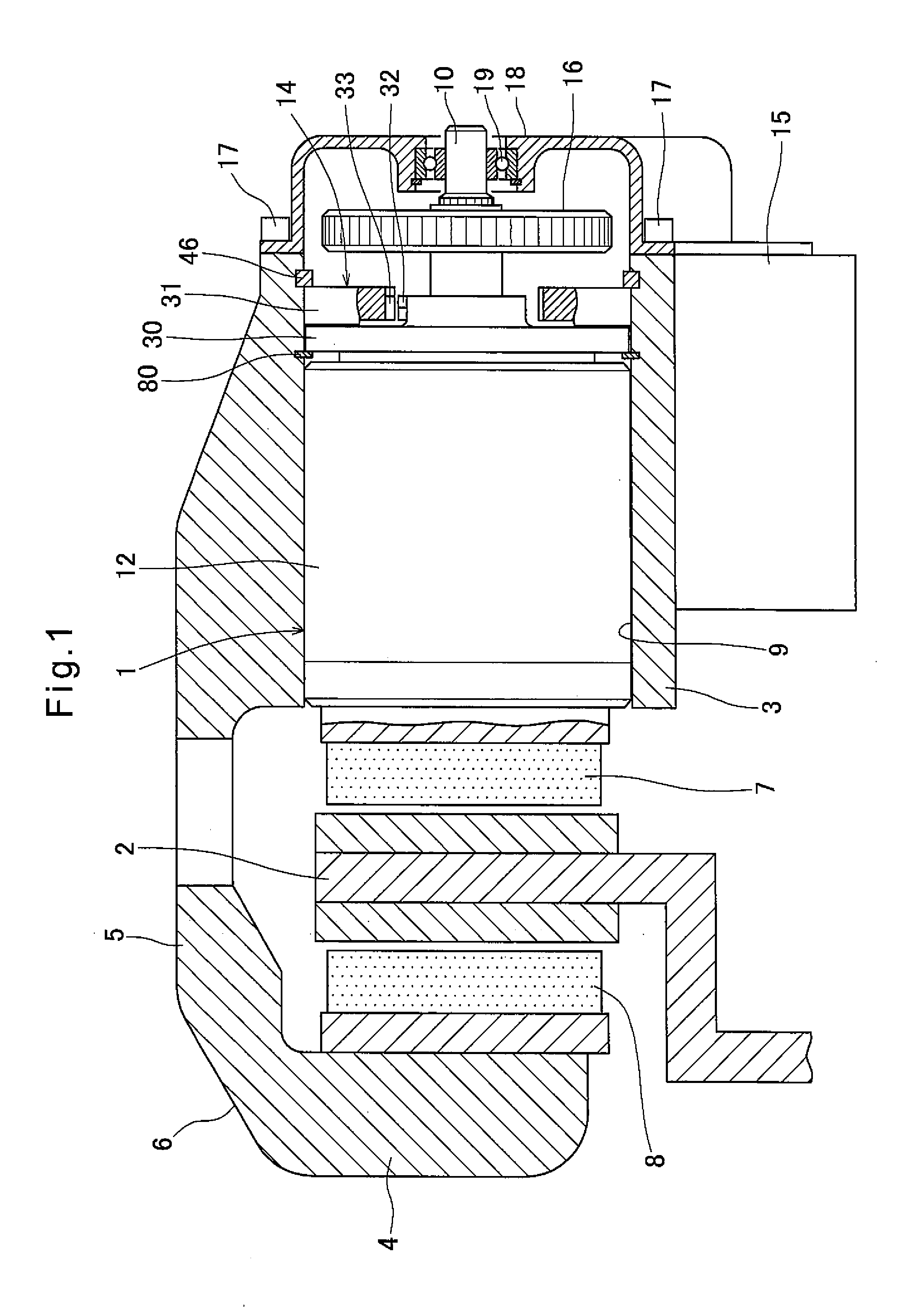
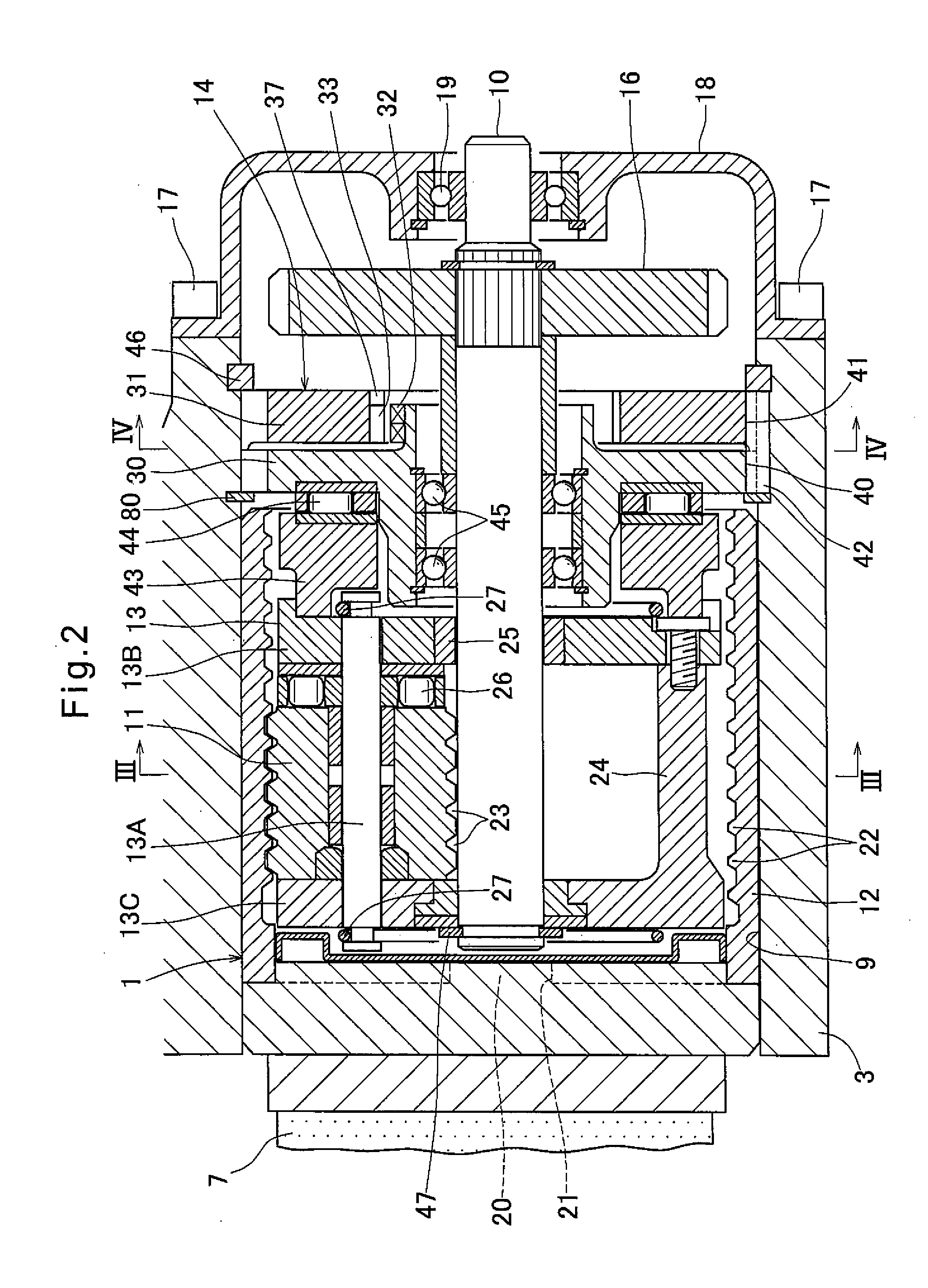
[0035]FIG. 1 shows an electric brake system for a vehicle including an electric linear motion actuator 1 embodying the present invention. This electric brake system includes a brake disk 2 adapted to rotate together with a vehicle wheel, a caliper body 6 having opposed pieces 3 and 4 facing each other with the brake disk 2 therebetween, and a bridge 5 through which the opposed pieces 3 and 4 are coupled together, and a pair of right and left friction pads 7 and 8. The electric linear motion actuator 1 is mounted in a mounting hole 9 formed in the opposed piece 3 and open to the surface of the opposed piece 3 facing the brake disk 2, and a pair of right and left friction pads 7 and 8.

[0036]The friction pads 7 and 8 are disposed between the opposed piece 3 and the brake disk 2 and between the opposed piece 4 and the brake disk 2, respectively, and supported by a mount (not shown) fixed to a knuckle (not shown either) supporting the wheel so as to be movable in the axial direction of t...


PUM


Abstract

An electric linear motion actuator is provided which can set the clearance during normal braking operation of an electric brake system. The linear motion actuator includes a load sensor for detecting the magnitude of the load with which a friction pad is pressed against the brake disk, a temperature sensor for compensating for the influence of temperature on the load sensor, and an electronic control unit. The electronic control unit is adapted to calculate a target rotational angle from the position of the electric motor corresponding to the magnitude of the load detected by the load sensor to the position of the electric motor where the clearance is at a predetermined value, and control the electric motor to rotate the electric motor by the target rotational angle.

Description

TECHNICAL FIELD[0001]This invention relates to an electric linear motion actuator capable of converting the rotary motion of a rotary shaft driven by an electric motor to a linear motion of a linear motion member, thereby pressing an object with the linear motion member, and an electric brake system including such an electric linear motion actuator.BACKGROUND ART[0002]Many of older vehicle brake systems are hydraulic brake systems, which include a brake disk and friction pads driven by hydraulic cylinders and pressed against the brake disk. But with the recent introduction of new brake control systems such as anti-lock brake systems (ABS), electric brake systems, which do not use hydraulic circuits, are gathering much attention.[0003]An electric brake system includes an electric linear motion actuator configured to covert the rotation of a rotary shaft driven by an electric motor to a linear motion of a linear motion member, thereby driving and pressing brake pads against a brake di...

Claims


Application Information

Patent Timeline
Patent Type & Authority Applications(United States)
IPC IPC(8): F16H25/22F16D65/14
CPCF16D65/14F16H25/2252F16D55/00F16D65/18F16D65/62F16D65/68F16D2066/003F16D2066/005F16D2121/24F16D2125/36F16D2125/40F16D2125/48F16H25/2021F16H25/2204
Inventor YAMASAKI, TATSUYAMASUDA, YUIMURAMATSU, MAKOTOEGUCHI, MASAAKISAOYAMA, YUKI
Owner NTN CORP
Why Eureka
Try Eureka