Powered vehicle brake cooling system

a technology for brake cooling and powered vehicles, applied in the direction of brake systems, brake discs, fluid actuated brakes, etc., can solve the problems that the open duct and inlet may have an adverse effect on the local streamlined air flow, and achieve the effect of rapid actuator response and facilitate the reverse transformation

Inactive Publication Date: 2014-09-18
GM GLOBAL TECH OPERATIONS LLC
View PDF15 Cites 24 Cited by
  • Summary
  • Abstract
  • Description
  • Claims
  • Application Information

AI Technical Summary

Benefits of technology

[0009]The inlet of the duct will generally be placed and attached at a location where there is an appreciable air flow around the moving vehicle. An example of one such location is at an air dam directing air flow under the engine compartment and passenger compartment floor. At such a duct inlet location, an open duct and inlet may have an adverse effect on the local streamlined air flow. Accordingly, the inlet or the duct will be closed by the closure member when brake cooling is not required. The closure may be positioned and adapted to cooperate with the inlet and / or duct to promote streamlined flow around the inlet. In many embodiments when no power is provided to the actuator the closure may be in its closed configuration and the vehicle in its aerodynamically clean configuration. However, in some embodiments it may be preferred to have the closure adopt its open configuration under power-off conditions to ensure that the supplementary brake cooling can never be lost.
[0010]As noted, the opening and closing of the closure is effected by an actuator incorporating an active material which undergoes a reversible phase change at a predetermined temperature or over a predetermined narrow temperature range. Commonly the heat will be generated electrically by provision of a portion of the on-vehicle battery power. In some embodiments, an external heater, such as a cartridge heater or a thermoelectric device, in thermal communication with the actuator may be used. A thermoelectric device, by reversal of the current flow may also be used for cooling to facilitate the reverse transformation. In SMA-based actuators current may be directed along the length of the electrically-conductive SMA element to generate Joule heating in the element. It will be appreciated that such Joule heating may quickly raise the element to its operating temperature and enable rapid actuator response.

Problems solved by technology

At such a duct inlet location, an open duct and inlet may have an adverse effect on the local streamlined air flow.

Method used


Image

  • Powered vehicle brake cooling system
  • Powered vehicle brake cooling system
  • Powered vehicle brake cooling system

Examples


Embodiment Construction

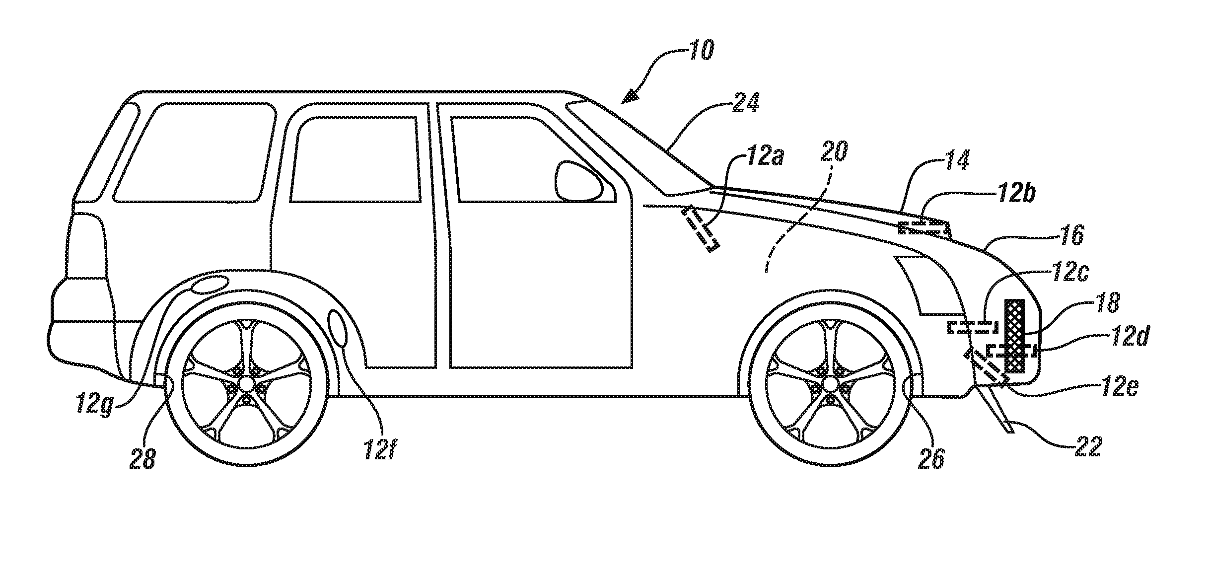
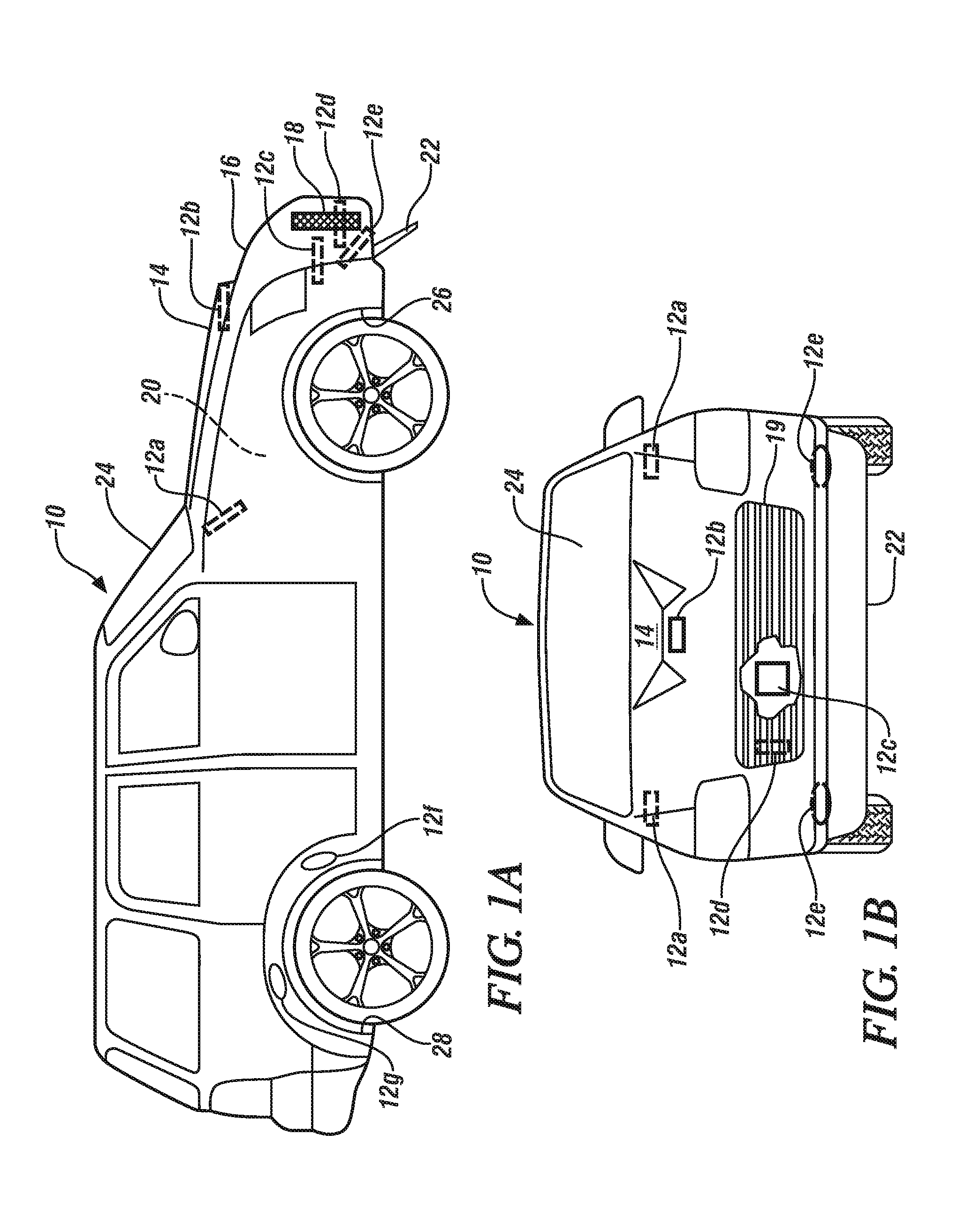
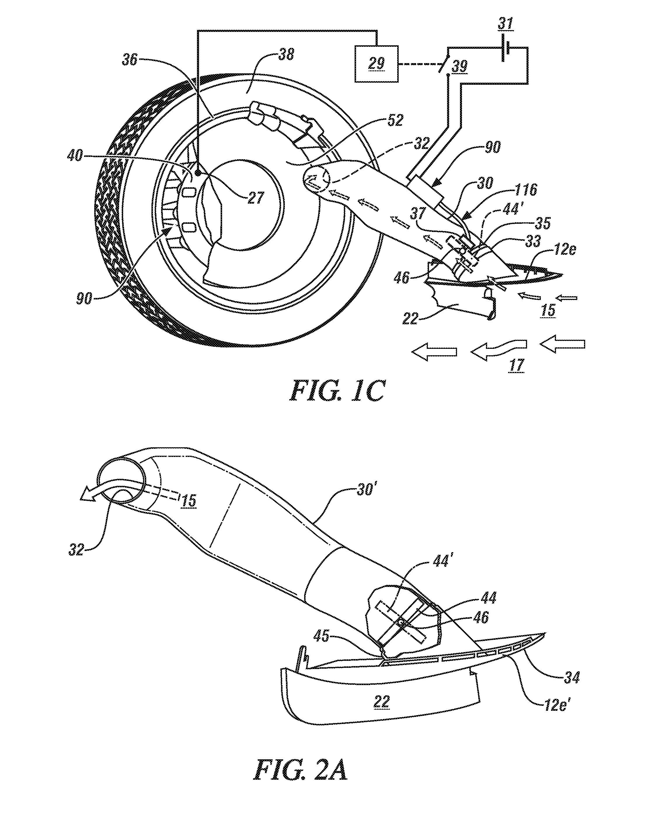
[0033]A method of providing supplementary cooling air to the brakes of a vehicle, when needed, is described. Typically this need will arise when the brakes attain and exceed a predetermined elevated temperature, but other, more anticipatory, strategies may also be used. These could include consideration of the time-derivative of brake temperature rise, or consideration of prior experience on a frequently-travelled route or even knowledge of, for example mountainous, terrain gleaned from an on-board GPS unit and suitable mapping software In the most readily implemented embodiment, a temperature sensor, in communication with a controller, senses the brake temperature and, when the sensed brake temperature exceeds a predetermined limit, the controller acts to enable a flow of cooling air to the brakes.

[0034]Manual implementation is also possible. An operator-selectable switch might be used to select or deselect the cooling air. Where a vehicle provides the operator a choice of performa...


PUM


Abstract

An inlet, positioned to access the flow of air passing around and under a moving vehicle, may draw in air which is conveyed through a duct and discharged to cool a brake on a vehicle. The inlet has a closure. The closure is opened and closed on demand by a temperature-operated actuator incorporating an active or smart material under the direction of a controller. In embodiments, a sensor, suitably positioned to sense a temperature representative of the brake temperature, communicates the sensed brake temperature to the controller. The controller may respond to the sensed brake temperature, by triggering operation of the actuator. Typically the closure is opened to allow passage of cooling air to the brake when the sensed brake temperature exceeds, or is anticipated to exceed, a predetermined temperature.

Description

TECHNICAL FIELD[0001]This disclosure pertains to a duct system with a powered closure for directing ambient air, on demand, to brakes on the wheels of the vehicle. More specifically, at least one actuator incorporating a reversible temperature sensitive active material, a controller and a sensor, cooperatively act to open and close the closure in the airflow duct system to provide cooling air, taken from the air flow around the moving automotive vehicle, to the vehicle brakes. The cooling air is provided, as needed, to maintain the brake temperature in a preferred operating range.BACKGROUND OF THE INVENTION[0002]Modern automotive vehicles typically have hydraulically actuated brakes on both the front and rear wheels of the vehicle. In vehicle disc brake systems, the hub of the vehicle wheel is mounted to an axially concentric, circular disc formed of a thermally conductive and wear resistant metal. A brake caliper, fixed to the vehicle, fits around a sector of the circular disc. Whe...

Claims


Application Information

Patent Timeline
Patent Type & Authority Applications(United States)
IPC IPC(8): F16D65/847
CPCF16D65/847B60T5/00
Inventor BROWNE, ALAN L.JUECHTER, TADGE J.JOHNSON, NANCY L.ALEXANDER, PAUL W.GAO, XIUJIESKURKIS, RICHARD J.BENNION, KIRK D.
Owner GM GLOBAL TECH OPERATIONS LLC
Why Eureka
Try Eureka