Semiconductor package and fabrication method thereof

Active Publication Date: 2014-09-18
SILICONWARE PRECISION IND CO LTD
View PDF2 Cites 12 Cited by
  • Summary
  • Abstract
  • Description
  • Claims
  • Application Information

AI Technical Summary

Benefits of technology

The present invention is about a new way of making semiconductor packages. By stacking semiconductor layers and then making the interposer that holds them thinner, the package becomes flatter without getting bent. This allows multiple chips to be put into the package, reducing production costs and increasing efficiency.

Problems solved by technology

However, in a flip-chip packaging process, conductive bumps of a semiconductor chip crack easily under thermal stresses caused by a big CTE (Coefficient of Thermal Expansion) mismatch between the semiconductor chip and the corresponding packaging substrate, thereby adversely affecting the formation of joints between the conductive bumps of the semiconductor chip and the correspondingly packaging substrate and easily resulting in delamination of solder bumps from the packaging substrate.
Further, along with increased integration of integrated circuits, CTE mismatches between chips and packaging substrates induce more thermal stresses and lead to more serious warpages, thereby reducing the product reliability and resulting in failure of reliability tests.
Accordingly, when the number of the chips increases, the area of the packaging substrate must be increased, which, however, does not meet the demands for miniaturization and high performance of electronic products.
On the other hand, the pitch between contacts of packaging substrates are only at the micrometer scale and cannot effectively match the pitch between the electrode pads of the semiconductor chips, thus adversely affecting the fabrication of electronic products.
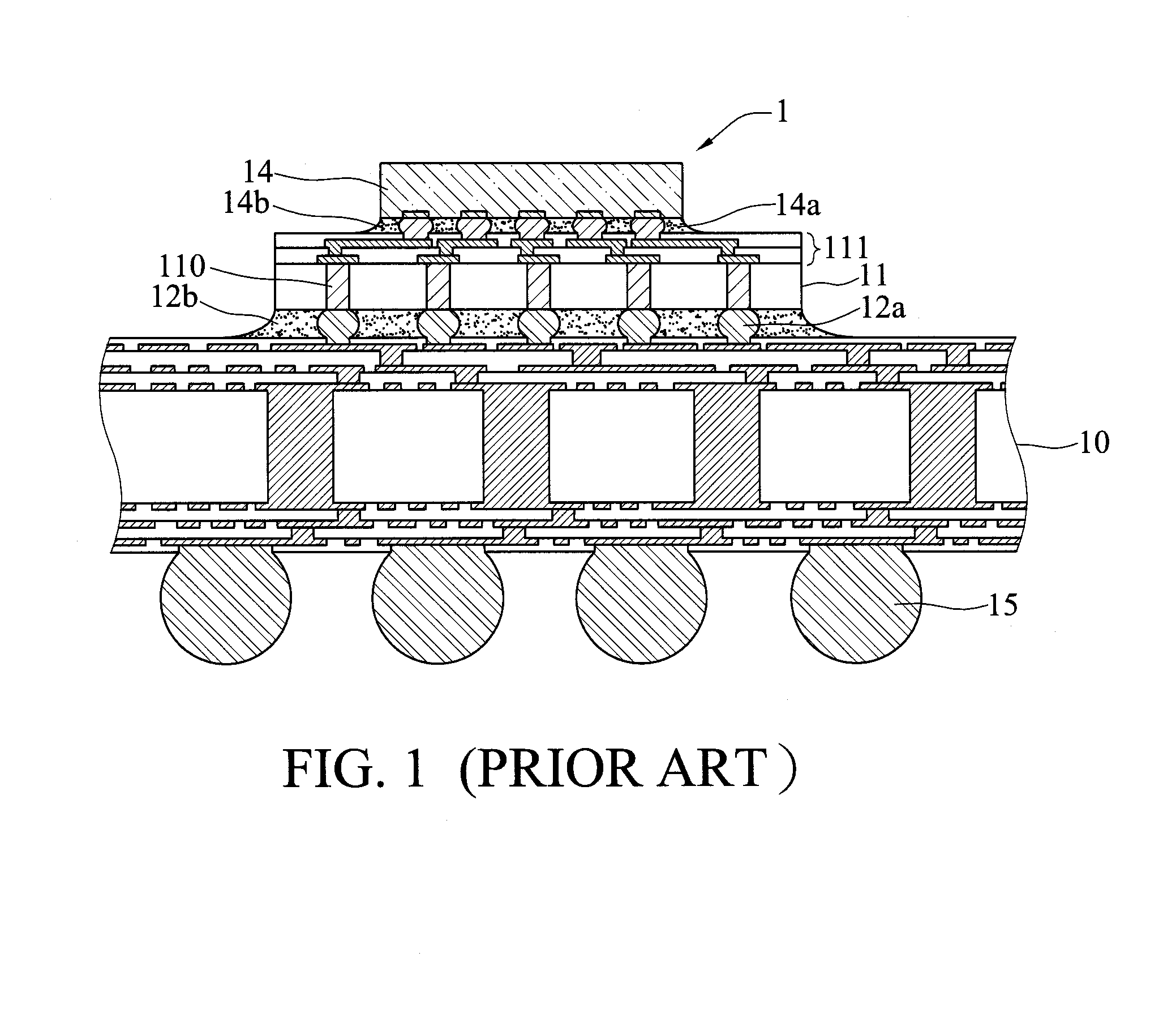
In addition, the fine-line / fine-pitch characteristic of the silicon interposer 2 leads to short electrical transmission distance and high electrical transmission speed of the semiconductor chip 14.
Therefore, warpage easily occurs to the silicon interposer 11 and consequently it is difficult to dispose and electrically connect the semiconductor chip 14 to the silicon interposer 11.
To overcome the drawbacks, the silicon interposer 11 is required to have a certain thickness, which, however, hinders the miniaturization of the semiconductor package 1.
Further, although a plurality of semiconductor chips 14 can be disposed on the silicon interposer 11 in a 2D manner to improve the product functionality, it cannot meet the multi-function requirement of electronic products.
Furthermore, to dispose a plurality of semiconductor chips 14 on the silicon interposer 11, the semiconductor chips 14 are conventionally ground first and then disposed on the silicon interposer 11 one by one, thereby greatly increasing the fabrication time and cost.
In addition, the semiconductor chips 14 may be thinned to different degrees and hence cannot provide an even surface for stacking and disposing of other chips.

Method used


Image

  • Semiconductor package and fabrication method thereof
  • Semiconductor package and fabrication method thereof
  • Semiconductor package and fabrication method thereof

Examples


Embodiment Construction

[0038]The following illustrative embodiments are provided to illustrate the disclosure of the present invention, these and other advantages and effects can be apparent to those in the art after reading this specification.

[0039]It should be noted that all the drawings are not intended to limit the present invention. Various modifications and variations can be made without departing from the spirit of the present invention. Further, terms such as “lower”, “first”, “second”, “a” etc. are merely for illustrative purposes and should not be construed to limit the scope of the present invention.

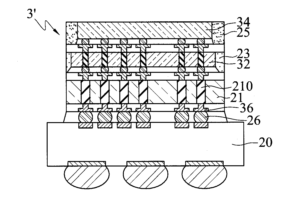
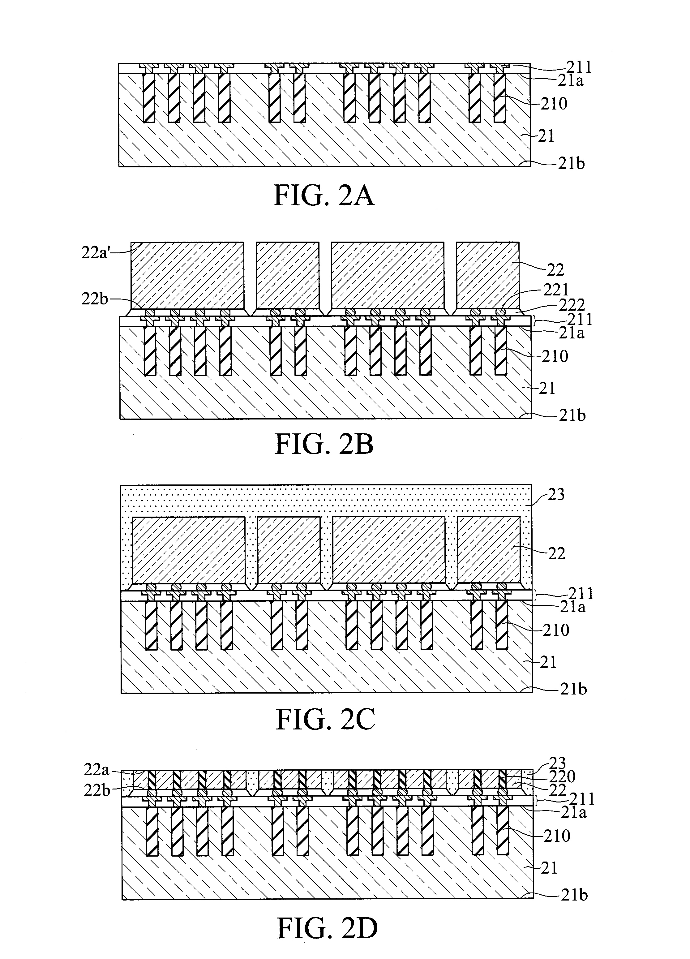
[0040]FIGS. 2A to 2K are schematic cross-sectional views showing a fabrication method of a semiconductor package 2, 2′ according to a first embodiment of the present invention.

[0041]Referring to FIG. 2A, an interposer 21 is provided, which has opposite first and second sides 21a, 21b and a plurality of first conductive through holes 210 that penetrate the first side 21a but do not penetrate the seco...


PUM


Abstract

A fabrication method of a semiconductor package is disclosed, which includes the steps of: disposing a plurality of first semiconductor elements on an interposer; forming a first encapsulant on the interposer for encapsulating the first semiconductor elements; disposing a plurality of second semiconductor elements on the first semiconductor elements; forming a second encapsulant on the first semiconductor elements and the first encapsulant for encapsulating the second semiconductor elements; and thinning the interposer, thereby reducing the overall stack thickness and preventing warpage of the interposer.

Description

BACKGROUND OF THE INVENTION[0001]1. Field of the Invention[0002]The present invention relates to semiconductor packages, and more particularly, to a semiconductor package having an interposer and a fabrication method thereof.[0003]2. Description of Related Art[0004]Along with the rapid development of electronic industries, electronic products are becoming lighter, thinner, shorter and smaller. To meet the demands for high integration and miniaturization of electronic products, various types of packages such as chip scale packages (CSPs), direct chip attached (DCA) packages and multi-chip module (MCM) packages have been developed by using flip-chip technologies so as to increase circuit densities, reduce chip packaging sizes and shorten signal transmission paths.[0005]However, in a flip-chip packaging process, conductive bumps of a semiconductor chip crack easily under thermal stresses caused by a big CTE (Coefficient of Thermal Expansion) mismatch between the semiconductor chip and ...

Claims


Application Information

Patent Timeline
IPC IPC(8): H01L21/52H01L21/56H01L23/28
CPCH01L21/52H01L23/28H01L21/563H01L2224/16225H01L2224/32225H01L2224/73204H01L2924/15174H01L2924/15311H01L23/3114H01L23/3128H01L21/486H01L25/065H01L23/49827H01L23/49833H01L2924/00H01L23/481H01L23/3135H01L25/50H01L25/0657H01L21/78
Inventor LIN, CHUN-TANGLAI, YI-CHE
Owner SILICONWARE PRECISION IND CO LTD
Why Eureka
Try Eureka