Piezoelectric element, liquid ejecting head, liquid ejecting apparatus, ultrasonic transducer, and ultrasonic device

a liquid ejecting head and liquid ejecting technology, which is applied in the direction of piezoelectric/electrostrictive/magnetostrictive devices, piezoelectric/electrostriction/magnetostriction machines, piezoelectric elements, etc., can solve the problems of deteriorating piezoelectric properties of the piezoelectric element, damage, and crystal defect, etc., to achieve the effect of improving performan

Inactive Publication Date: 2014-09-18
SEIKO EPSON CORP
View PDF3 Cites 22 Cited by
  • Summary
  • Abstract
  • Description
  • Claims
  • Application Information

AI Technical Summary

Benefits of technology

[0021]According to the aspect described above, the ultrasonic device is provided with the ultrasonic transducer having the piezoelectric e

Problems solved by technology

There is a possibility that such a piezoelectric element may be damaged due to the external environment, such as ink or moisture (humidity).
However, in a case in which the protection film is formed on the piezoelectric element by the sputtering method, there is a possibility that damage, such as a crystal defect, may be caused in the piezoelectric element by plasma generated when sputtering is performed.
When damage is caused in the piezoelectric element, as described above, the piezoelectric properties of the piezoelectric element

Method used


Image

  • Piezoelectric element, liquid ejecting head, liquid ejecting apparatus, ultrasonic transducer, and ultrasonic device
  • Piezoelectric element, liquid ejecting head, liquid ejecting apparatus, ultrasonic transducer, and ultrasonic device
  • Piezoelectric element, liquid ejecting head, liquid ejecting apparatus, ultrasonic transducer, and ultrasonic device

Examples


embodiment 1

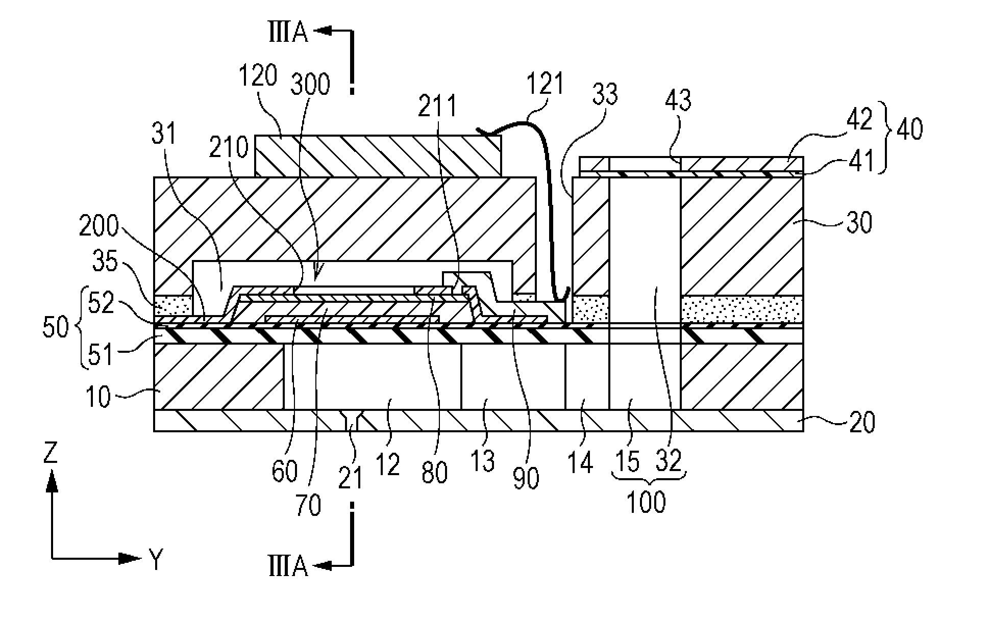
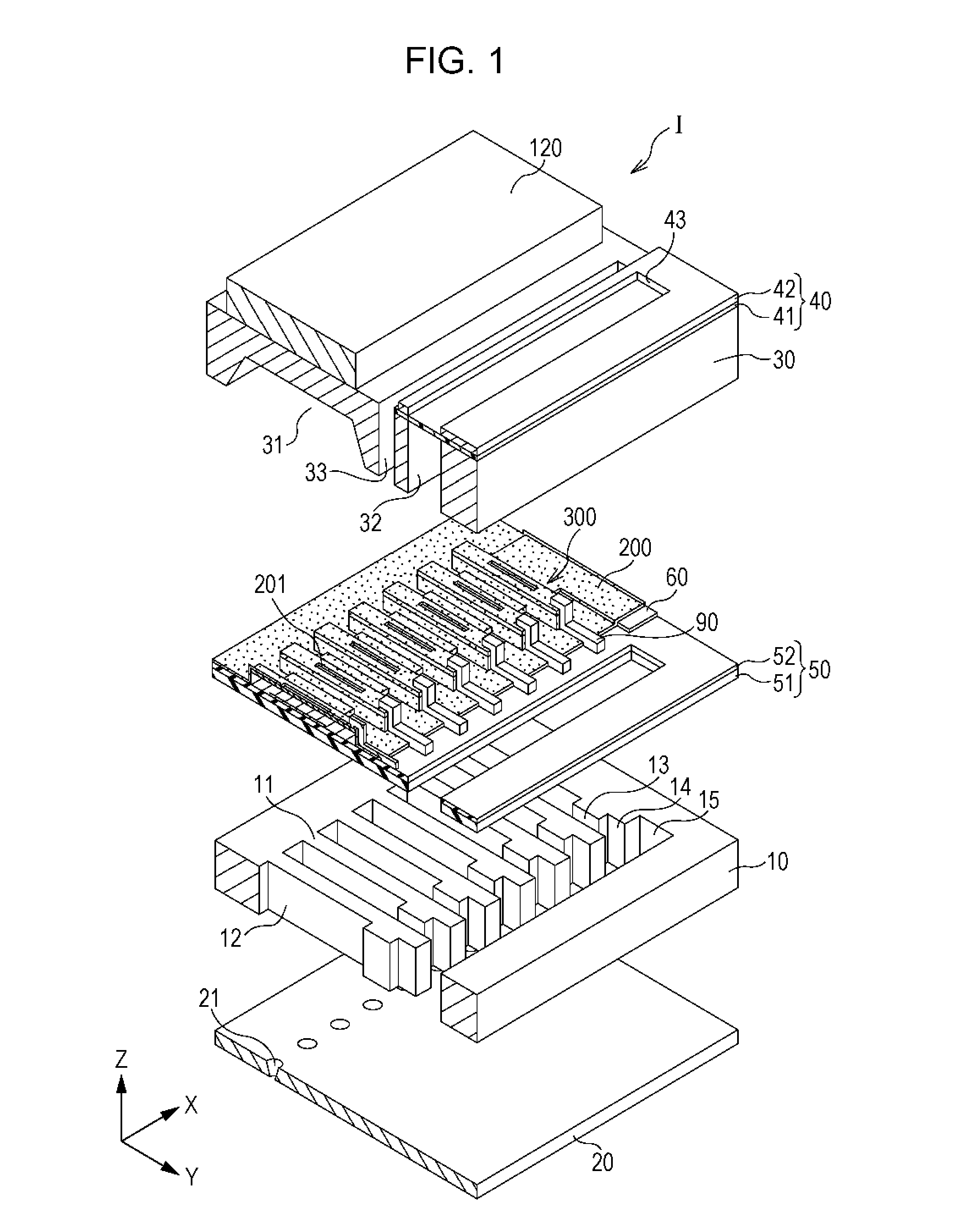
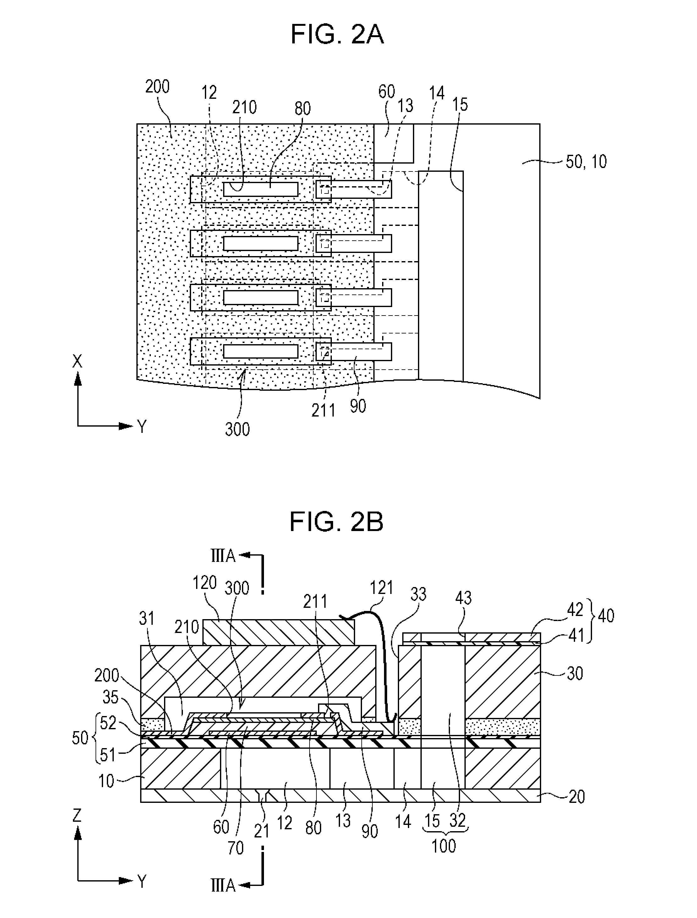
[0033]FIG. 1 is a perspective view of a head according to embodiment 1, and FIGS. 2A and 2B are a top view and a cross-sectional view of the head. In addition, a protection substrate 30 is not illustrated in the top view of the head, which is illustrated in FIG. 2.

[0034]A head I includes a flow-passage forming substrate 10 and pressure generating chambers 12 are formed in the flow-passage forming substrate 10, as illustrated in the drawings. The pressure generating chambers 12 are partitioned by a plurality of partition walls 11 and arranged in parallel along a direction in which a plurality of nozzle openings 21 through which ink is discharged are arranged in parallel. Hereinafter, this direction is referred to as a parallel arrangement direction of the pressure generating chambers 12 or a first direction X. In addition, in a plane of the flow-passage forming substrate 10, a direction perpendicular to the first direction X is set to be a second direction Y. Furthermore, a direction...

embodiment 2

[0076]In the description of the embodiment 1, a case in which the protection film 200 is formed on the piezoelectric element 300 of which the first electrode 60 is a common electrode and the second electrodes 80 are individual electrodes is exemplified. In the description of embodiment 2, a case in which a protection film 200A is formed on the piezoelectric element 300 of which the first electrode 60 is an individual electrode and the second electrodes 80 is a common electrode will be exemplified.

[0077]FIGS. 7A and 7B are a cross-sectional view of the head according to the embodiment 2 and an enlarged cross-sectional view illustrating principal portions thereof. In addition, the same reference numerals are given to the same members as those in the embodiment 1, and the same descriptions will not be repeated.

[0078]The first electrodes60 constituting the piezoelectric element 300 are separated for each pressure generating chamber 12 and constitutes an individual electrode separated fo...

embodiment 3

[0089]An ultrasonic transducer which is an embodiment of the invention and an ultrasonic device equipped with the ultrasonic transducer will be described. In addition, an embodiment described below is not intended to limit the contents of the invention, which are described in the claims. Also, it is difficult to say that all of the components described in the embodiment are essential as solving means of the invention. In addition, the same reference numerals are given to the same members as those in the embodiment 1 described above, and the same descriptions will not be repeated.

[0090]In embodiment 3, transmission and reception of ultrasonic waves are performed by an electroacoustic transducer using a piezoelectric effect. The electroacoustic transducer is a piezoelectric element. When transmitting the ultrasonic waves, the piezoelectric element uses the conversion (an inverse piezoelectric effect) of electric energy into mechanical energy. The change caused by contraction and exten...


PUM


Abstract

Provided is a piezoelectric element which includes a first electrode, a piezoelectric body layer provided on the first electrode, a second electrode provided on the piezoelectric body layer, and a protection film constituted by a silicon oxide layer that is formed using trimethoxysilane and a liquid-phase zirconia layer, in which the protection film is formed to extend from upper portions of the first electrode and the second electrode to boundary portions between the electrodes and the piezoelectric body layers.

Description

BACKGROUND[0001]1. Technical Field[0002]The present invention relates to a piezoelectric element, a liquid ejecting head, a liquid ejecting apparatus, an ultrasonic transducer, and an ultrasonic device.[0003]2. Related Art[0004]A liquid ejecting head in which a piezoelectric element is deformed to cause pressure fluctuation of liquid in a pressure generating chamber, and thus liquid droplets are ejected from nozzles communicating with the pressure generating chamber has been known. A representative example of the liquid ejecting head includes an ink-jet type recording head in which ink droplets are ejected as the liquid droplets.[0005]Such an ink-jet type recording head includes, for example, a piezoelectric element on one surface side of a flow-passage forming substrate in which a pressure generating chamber communicating with nozzle openings is provided. This ink-jet type recording head causes ink droplets to be ejected from nozzles in a manner such that a vibrating plate is defor...

Claims


Application Information

Patent Timeline
IPC IPC(8): B41J2/14H01L41/053
CPCH01L41/0533B41J2/14201B41J2/14233B41J2002/14241B41J2202/03B41J2202/11H10N30/883H10N30/2047
Inventor OHASHI, KOJIHIRAI, EIJU
Owner SEIKO EPSON CORP
Why Eureka
Try Eureka