System and Methods for Two-Stage Buck Boost Converters with Fast Transient Response

a converter and transient response technology, applied in the field of power supplies, can solve the problems of large die size, low efficiency, unsatisfactory transient response,

Active Publication Date: 2014-09-18
MAXIM INTEGRATED PROD INC
View PDF2 Cites 31 Cited by
  • Summary
  • Abstract
  • Description
  • Claims
  • Application Information

AI Technical Summary

Benefits of technology

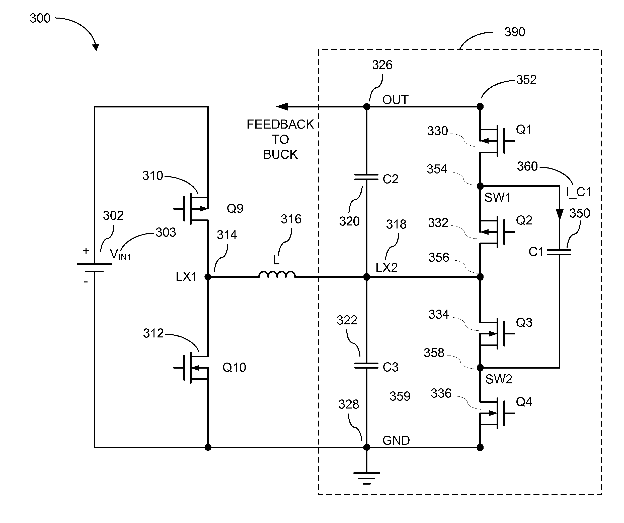
[0009]One particular embodiment takes advantage of a dual phase charge pump architecture in which each phase switches at 50% duty cycle, each phase operates at 50% duty cycle, and both phases operate 180 degrees out of phase with respect to each other when driving a constant DC load current. As a result, due to the lack of current pulses, an additional advantage of the dual phase charge pump is that there are virtually no ripple currents or di / dt induced ringing voltages present that could generate EMI noise. Instead, only DC load currents flow to the output. Additionally, efficiency is increased as the current flowing through each leg is only half of that of embodiments using a single phase charge pump.
[0010]Compared to conventional high voltage MOSFET applications, efficiency is also increased for any given silicon die area by the ability to size semiconductor devices to relatively low voltage ratings. This allows to significantly reduce switching current related losses associated with capacitances internal to MOSFETs. In certain embodiments, the charge pump is configured to operate in bypass mode to further enhance overall efficiency in instances when the input voltage is lower than the desired output voltage.

Problems solved by technology

However, common to these approaches is that they suffer from large die size, low efficiency, unsatisfactory transient response, and high output voltage ripple.

Method used


Image

  • System and Methods for Two-Stage Buck Boost Converters with Fast Transient Response
  • System and Methods for Two-Stage Buck Boost Converters with Fast Transient Response
  • System and Methods for Two-Stage Buck Boost Converters with Fast Transient Response

Examples


Embodiment Construction

[0020]In the following description, for the purpose of explanation, specific details are set forth in order to provide an understanding of the invention. It will be apparent, however, to one skilled in the art that the invention can be practiced without these details. One skilled in the art will recognize that embodiments of the present invention, described below, may be performed in a variety of ways and using a variety of means. Those skilled in the art will also recognize that additional modifications, applications, and embodiments are within the scope thereof, as are additional fields in which the invention may provide utility. Accordingly, the embodiments described below are illustrative of specific embodiments of the invention and are meant to avoid obscuring the invention.

[0021]Reference in the specification to “one embodiment” or “an embodiment” means that a particular feature, structure, characteristic, or function described in connection with the embodiment is included in ...


PUM


Abstract

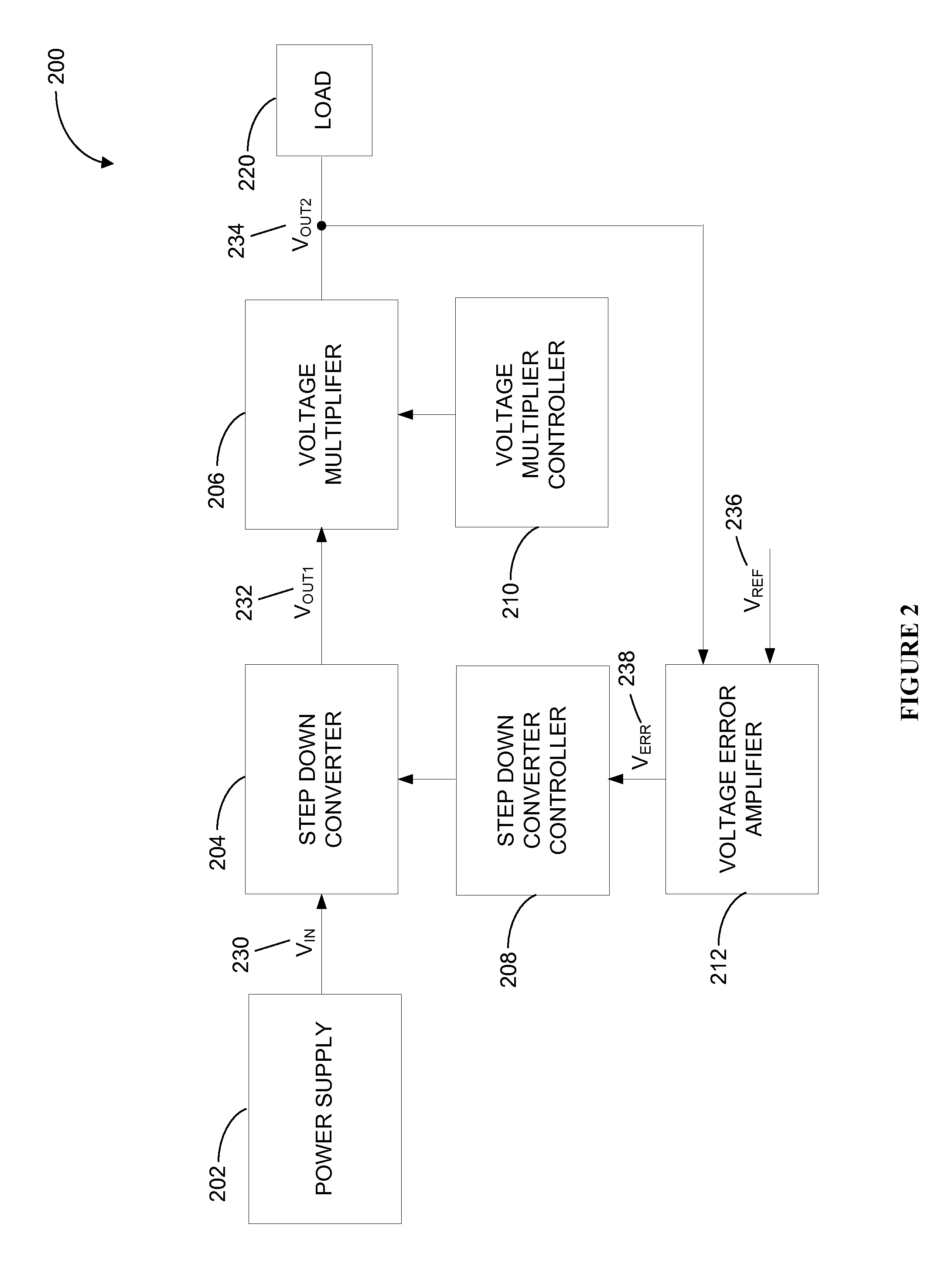
Various embodiments of the invention provide for single and dual phase charge pump, two stage DC / DC buck-boost converters having fast line and load transient control irrespective of load conditions. In certain embodiments of the invention, this is accomplished by controlling a desired output voltage with an error amplifier that controls a plurality of hysteresis comparators. A dual phase charge pump architecture eliminates ripple currents and mode transitions and increases efficiency by splitting the total current between two paths. Certain embodiments allow to use low voltage semiconductor devices, which significantly reduces switching losses and further increases efficiency.

Description

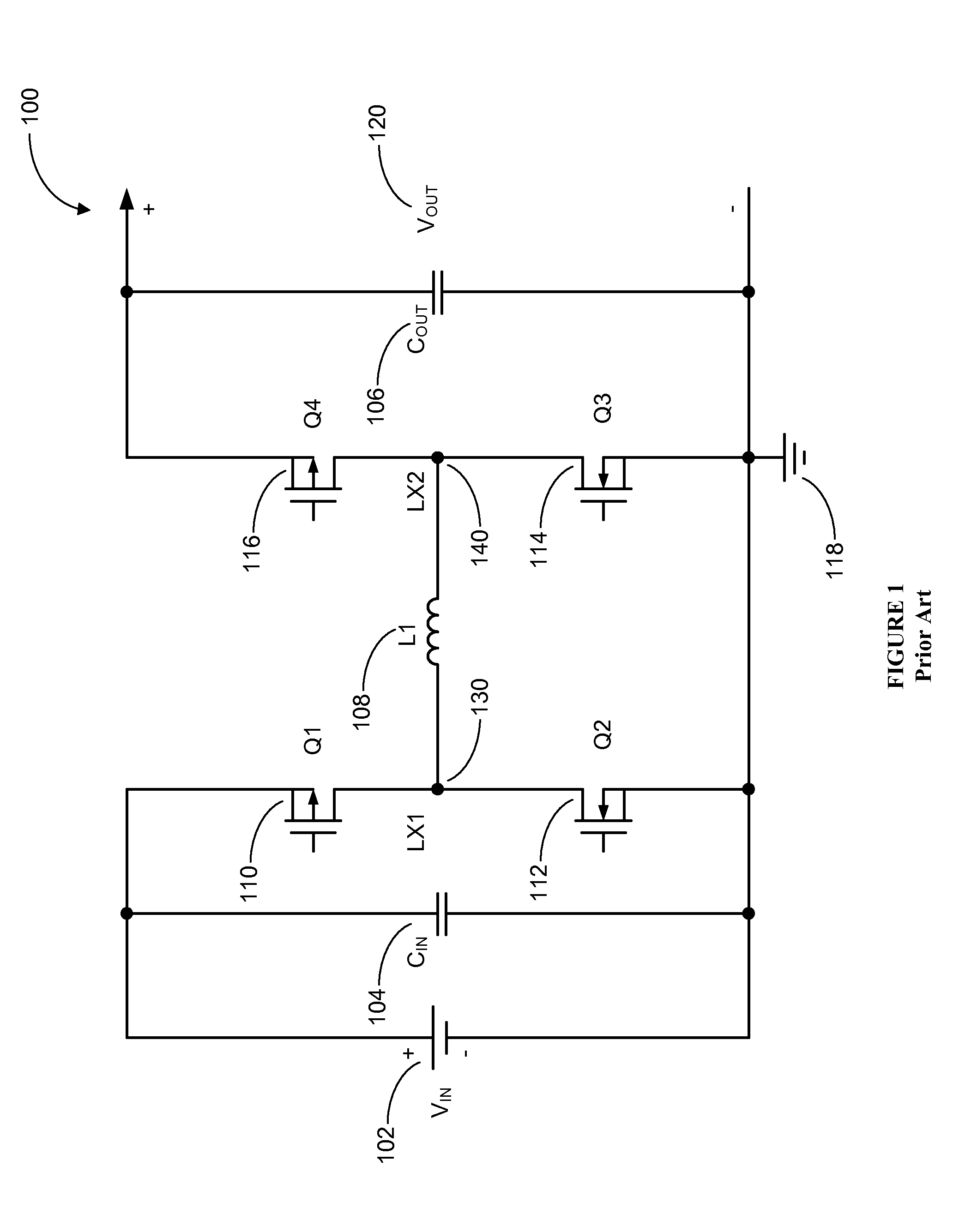
CROSS REFERENCE TO RELATED PATENT APPLICATIONS[0001]The present application claims priority to U.S. Provisional Application Ser. No. 61 / 785,831 titled “System and Methods for Two-Stage Buck Boost Converters with Fast Transient Response,” filed on Mar. 14, 2013 by Rui Liu, which application is incorporated herein by reference in its entirety.BACKGROUND[0002]A. Technical Field[0003]The present invention relates to power supplies, and more particularly, to systems, devices, and methods boost-buck converters for fast transient response and seamless transitions.[0004]B. Background of the Invention[0005]Many modern electronic consumer products require power from a regulated and accurate DC voltage sources capable of maintaining tight voltage regulation when subjected to fast transients. Oftentimes, the DC voltage must be stepped up by a boost converter or down to another DC voltage by a buck converter. When the output voltage must be capable of operating at lower and higher and voltages, ...

Claims


Application Information

Patent Timeline
Patent Type & Authority Applications(United States)
IPC IPC(8): H02M3/00
CPCH02M3/1582H02M3/07
Inventor LIU, RUI
Owner MAXIM INTEGRATED PROD INC
Why Eureka
Try Eureka