Planar-Magnetic Transducer With Improved Electro-Magnetic Circuit

a technology of electromagnetic circuit and transducer, applied in the direction of transducer details, electrical transducers, plane diaphragms, etc., can solve the problems of reducing the accuracy of high frequency amplitude response, affecting the operation of the diaphragm, so as to improve the excursion capability of the complete diaphragm, improve the control of the diaphragm, and increase the efficiency and available drive force of the diaphra

Active Publication Date: 2014-09-18
CROFT III JAMES J
View PDF8 Cites 12 Cited by
  • Summary
  • Abstract
  • Description
  • Claims
  • Application Information

AI Technical Summary

Benefits of technology

[0012]The present invention provides a double-sided drive planar magnetic transducer with an acoustically transparent primary output side. The structure of the present invention provides a planar-magnetic transducer with a frame and a primary magnet structure including magnets adjacent to, and air-gapped from, a first surface side of the mobile portion of a thin film or substantially planar diaphragm with conductive traces integrated with, and distributed across a portion of the diaphragm. The diaphragm is attached around a periphery of the mobile portion of the diaphragm and held in a state of predetermined tension. At least one secondary magnetic structure is mounted on a plane relative to a second surface side of the diaphragm and outside of the edge of the vibratable portion of the diaphragm to realize a second side drive to increase in force applied at least near the outer edge of the mobile portion of the diaphragm to improve diaphragm control and / or to increase the excursion capability of the complete diaphragm by creating a more planar diaphragm formation under high drive levels. The magnetic circuit at the outermost portion of the transducer can more effectively elevate the strongest flux lines up into the plane of the diaphragm, increasing efficiency and available drive force to the diaphragm.
[0013]In one preferred embodiment this increase in force can be at least partially derived from an increase in the flux density or “B” of the “BL” electromagnetic force at the outermost region of the mobile portion of the diaphragm, increasing excursion to create a more even, planar movement of the diaphragm by way of an additional magnetic source connected to the frame outside of the periphery of attachment of the film diaphragm and above the plane of an opposite, second surface side of the diaphragm to enhance double side magnetic energy drive force near the termination edge of the film diaphragm without any magnets in front of, the second side of the vibratable portion of the diaphragm which would interfere with the frontally projected acoustic waves of the device. The additional magnetic sources may be realized by, one or more of; a magnetically conductive pole and a magnet above the plane of the second surface side of the diaphragm or an acoustically transparent, magnetically conductive pole suspended over a second surface side of the diaphragm to increase drive to the diaphragm without any magnets suspended over the mobile portion of the second surface side of the diaphragm.
[0014]The invention provides for a wave-launch unimpeded by magnets on a second side of the vibratable portion of the diaphragm while having the advantage of an outboard magnetic circuit forward of the plane of the second surface side of the diaphragm providing a push-pull, double side drive along the outside portion of the diaphragm, or across the majority of both sides of the diaphragm, creating one or more of greater diaphragm control, more planar output and increased total output, without the drawbacks of acoustic interference of a double side drive system of the prior art. These and other forms and advantages will become apparent with the ongoing specification and claims disclosed below.

Problems solved by technology

Due to having magnets on both surface sides of the diaphragm, prior art double-ended devices can result in an increased and more confined magnetic field, but in exchange for the greater magnetic force they have had a number of limitations.
Those shortcomings include a reduced ability to reproduce high frequencies accurately without linear distortions due to acoustic blockage and cavity effects from magnet structures both behind and in front of the vibratable diaphragm reducing acoustic transparency and causing cavity resonances, which can cause aberrations in the high frequency amplitude response and a low pass filter characteristic that can reduce high frequency bandwidth.
Additional structural problems are caused by magnetic repulsion forces between the opposing front and back magnet structures centered over the active region of the diaphragm, particularly when high energy magnets are used, which require extensive bracing and / or heavy frame materials to attempt to offset frame flexing and minimize instabilities of diaphragm tension.
Both single-sided and double-sided prior art devices have a common limitation in that they tend to drive the active portion of the diaphragm with weaker force and / or reduced displacement at the outer most edge of the diaphragm and therefore, diaphragm excursions the center of the diaphragm can be much greater than at the outer portions of the diaphragm, causing both less effective use of diaphragm area, and a dynamic non-linear distortion due to changes in effective diaphragm area relative to diaphragm excursion.
Both single-ended and double-ended, devices also tend to have losses due to end conductor traces needing to be routed outside of the magnetic fields and causing resistive losses and un-driven portions of the diaphragm.
Additional limitations of prior art planar-magnetic transducers relate to reflections and standing waves that are due to film edge termination problems due to under-damped, uncontrolled diaphragm energy near the diaphragm edge termination points.
Also, the strongest flux lines at the outer most portion of the film diaphragm most often have the greatest intensity above or below, rather than in the plane of the film diaphragm such that they don't effectively engage the conductive traces on the diaphragm, and therefore contribute very little to the driving force of the outer portion of the diaphragm.
This can result in reduced acoustic output and also in less control of the outer portions of the diaphragm, potentially causing frequency response errors.
Additionally, single-end driven planar magnetic transducers, generally do not have the magnetic force and output capability of a double-ended device.
Solutions to the lack of diaphragm control have included mechanical damping of the film surface area and tend to be very lossy and raise the effective moving mass, which may cause further inefficiencies and limited control and utilization of the total diaphragm surface area.
Also, as planar magnetic devices are made larger or wider to increase output, they tend to lose dispersion in the upper frequency ranges and in some cases beam the sound forward with overly restrictive directivity.
These approaches can offset part of the amplitude response problems of double-ended devices but still do not equal a one side, fully open, single-ended device in this regard.

Method used


Image

  • Planar-Magnetic Transducer With Improved Electro-Magnetic Circuit
  • Planar-Magnetic Transducer With Improved Electro-Magnetic Circuit
  • Planar-Magnetic Transducer With Improved Electro-Magnetic Circuit

Examples


Embodiment Construction

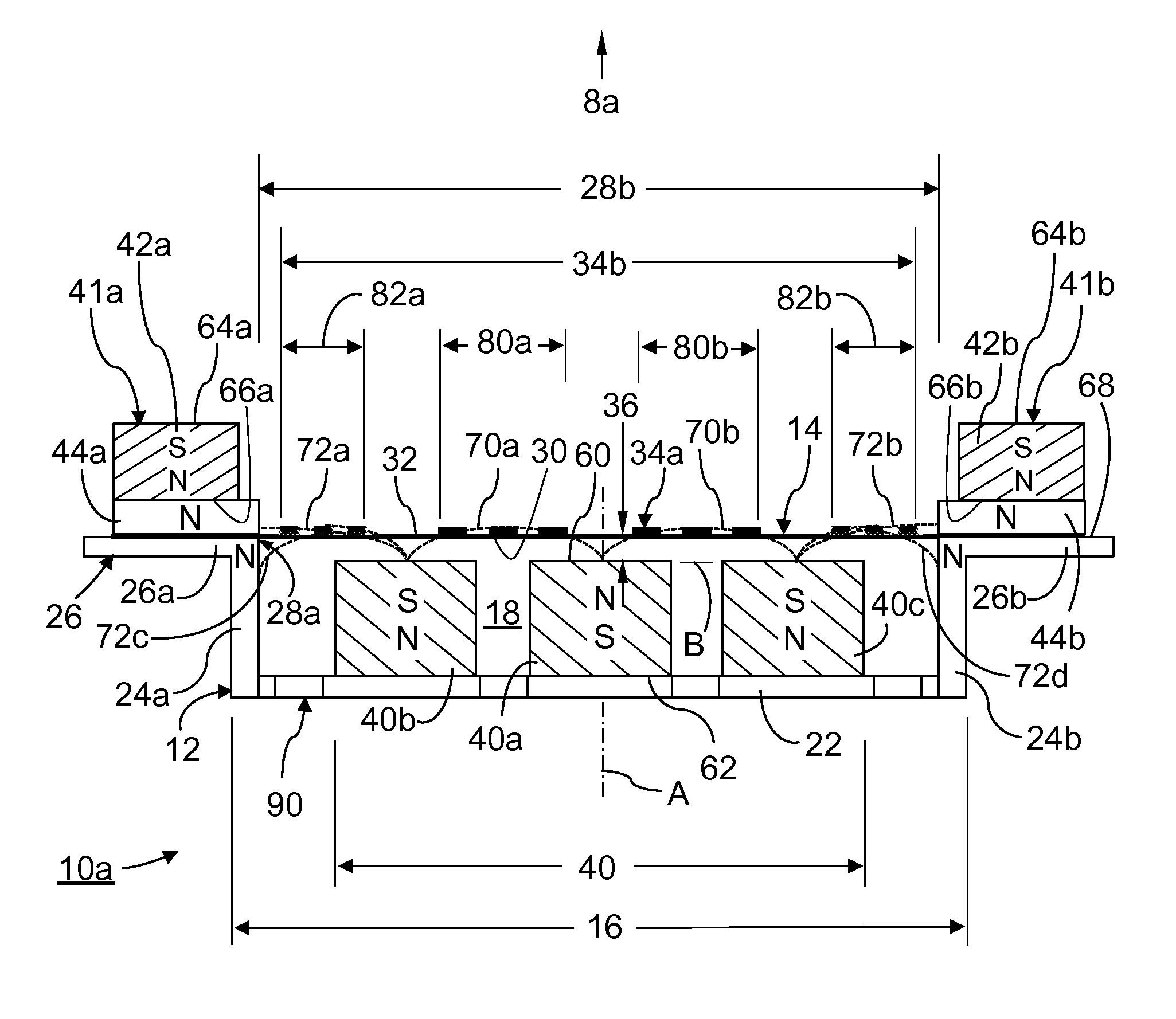
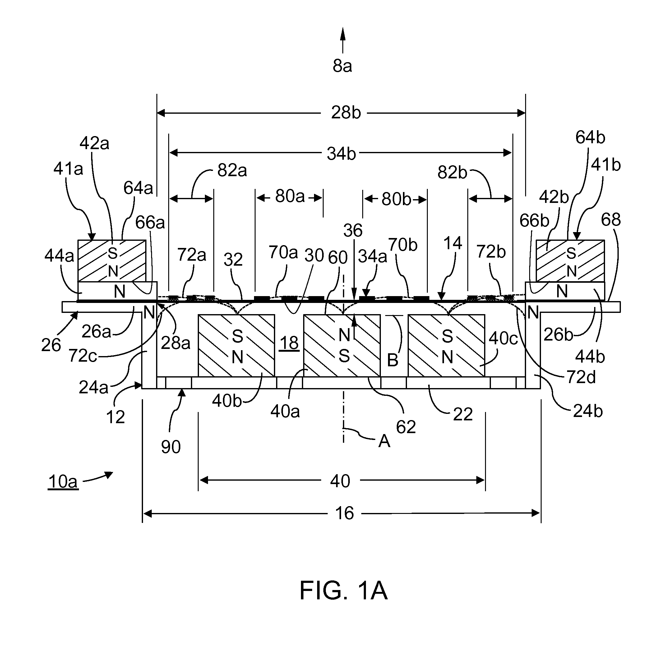
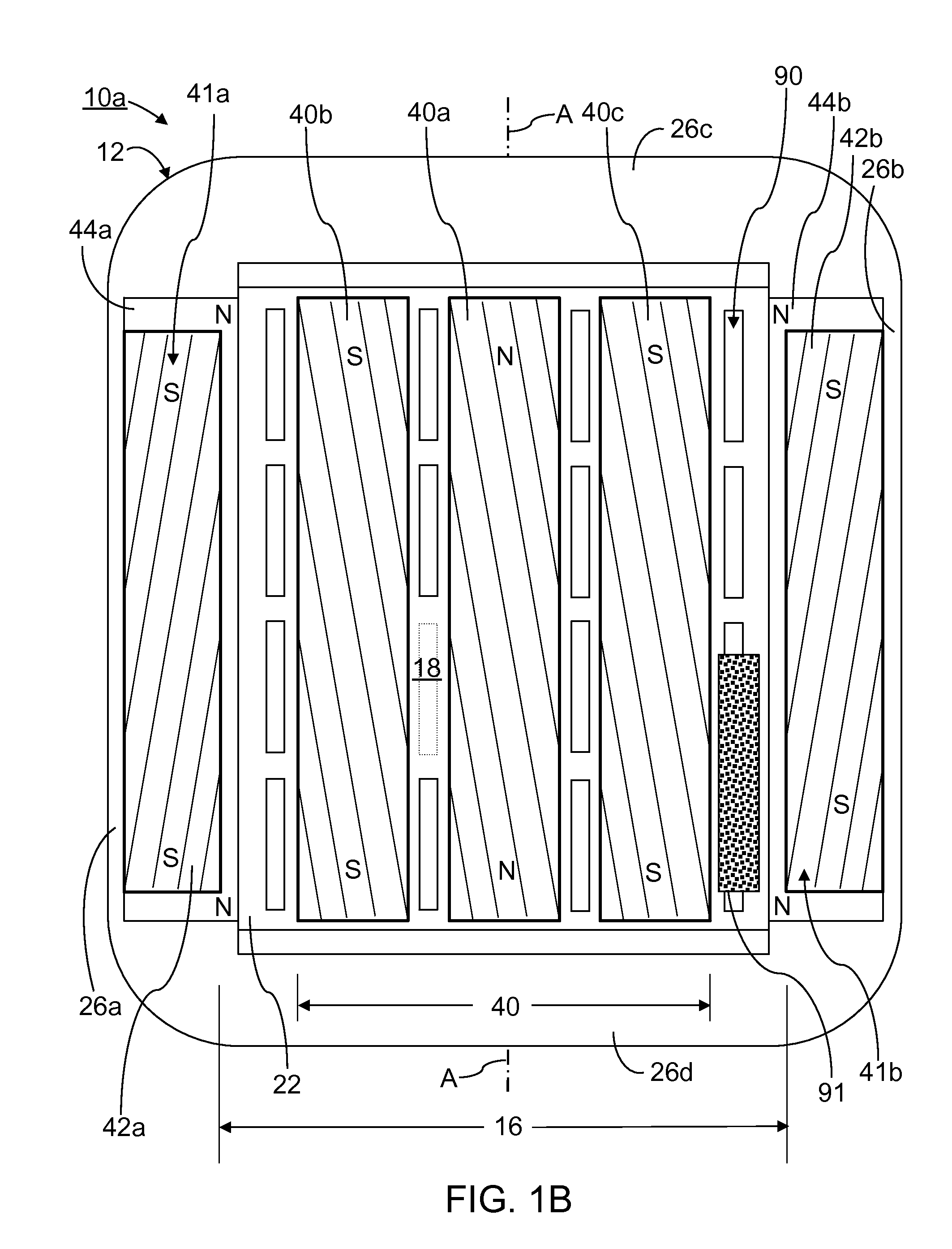
[0046]Referring initially to FIGS. 1A and 1B of the drawings, depicted therein is a first example of a quasi-double-sided drive, planar magnetic transducer 10a of the present invention. The first example transducer 10a comprises a frame 12, a diaphragm 14, and a primary magnetic structure 16. As depicted in FIG. 1A, a center-plane ‘A’ is defined with reference to the first example transducer 10a. A dimension of the example transducer 10a perpendicular to the center plane ‘A’ and substantially parallel to the diaphragm 14 will be referred to as a first, lateral, or width, X-axis reference direction. A direction along the center plane ‘A’ substantially perpendicular to the diaphragm will be referred to as a second, depth, or height, Y-axis reference dimension of the example transducer 10a. A dimension of the example transducer 10a parallel to the center plane ‘A’ and substantially parallel to the diaphragm 14 will be referred to as a third, longitudinal, or length, Z-axis reference di...


PUM


Abstract

The invention provides a planar-magnetic transducer with a frame and a primary magnet row structure of elongated magnets adjacent and air gapped from a first surface side of a mobile portion of a thin film or thin structure diaphragm with conductive traces incorporated with the diaphragm. An additional pair of magnetic sources attached to the frame outside of the vibratable region of the diaphragm and mounted above the plane of the opposite, second surface side of the diaphragm to enhance magnetic energy near the second surface side of the film diaphragm, without any magnet rows attached directly in front of the second surface side of the vibratable region of the diaphragm between the additional pair of magnetic sources. The additional magnetic sources can increase the drive force to the outer portions of the vibratable diaphragm, or across the diaphragm, to provide more control near the termination edge of the diaphragm and to create a more planar displacement of the diaphragm and increase transducer efficiency.

Description

RELATED APPLICATIONS[0001]This application (Attorney's Ref. No. P217856) claims benefit of U.S. Provisional Application Ser. No. 61 / 792,561 filed Mar. 15, 2013, the contents of which are incorporated herein by reference.TECHNICAL FIELD[0002]The present invention relates to planar magnetic loudspeaker transducers and systems, and more particularly, planar-magnetic transducers with flexible thin film diaphragms and conductive voice coil traces distributed across the thin film diaphragm.BACKGROUND AND RELATED ART[0003]In the field of planar-magnetic loudspeakers, the prior art has been primarily made up of what are referred to as double-ended (or double-side driven), and single-ended (or single-side driven) devices, referring to either groups of magnet rows adjacent both surface sides of a thin film diaphragm, in the double-ended case, or magnet rows adjacent just one surface side of the diaphragm, representing a single-ended layout. Examples of both of these approaches are illustrated...

Claims


Application Information

Patent Timeline
Patent Type & Authority Applications(United States)
IPC IPC(8): H04R9/06H04R9/04H04R7/16H04R9/02H04R1/00H04R7/04
CPCH04R9/06H04R1/00H04R7/04H04R2307/021H04R9/025H04R9/046H04R2400/00H04R7/16
Inventor CROFT, III, JAMES J.
Owner CROFT III JAMES J
Why Eureka
Try Eureka