Welded Stent and Stent Delivery System

Active Publication Date: 2014-09-18
MEDTRONIC VASCULAR INC
View PDF3 Cites 1 Cited by
  • Summary
  • Abstract
  • Description
  • Claims
  • Application Information

AI Technical Summary

Problems solved by technology

Soon after the procedure, however, a significant proportion of treated vessels re-narrow.
Unfortunately, nitinol is difficult to weld because nitinol forms an oxide layer on its surface that makes it difficult for the melt of the weld pool to reach the base metal during the welding process and achieve a good weld.
Further, nitinol welds tend to be brittle, increasing the chance of weld failure.
Welding difficulties can increase stent manufacturing costs due to increased manufacturing time and added quality control requirements.
Poor welds can also decrease the performance of stents in use should the welds fail a

Method used


Image

  • Welded Stent and Stent Delivery System
  • Welded Stent and Stent Delivery System
  • Welded Stent and Stent Delivery System

Examples


Example

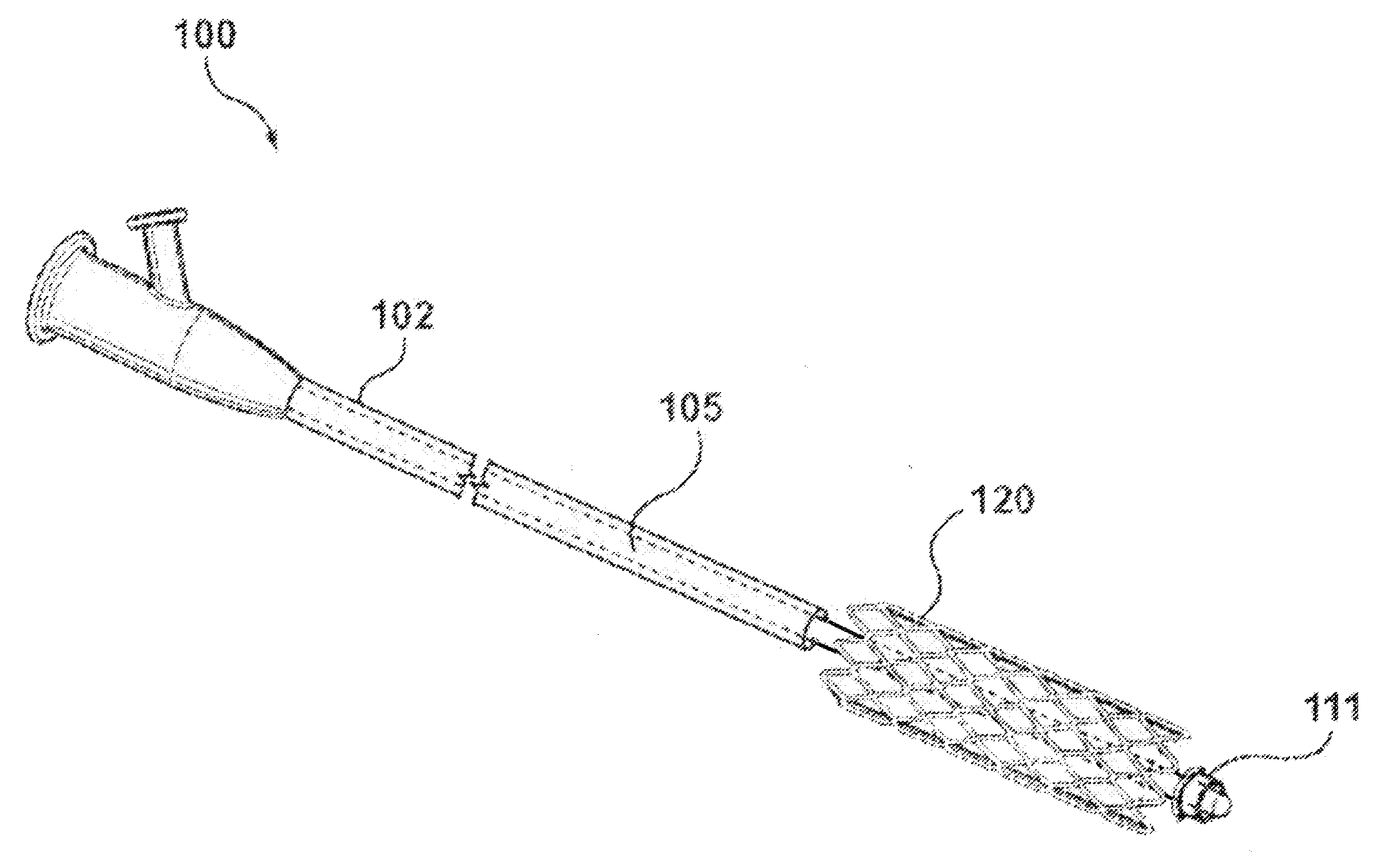
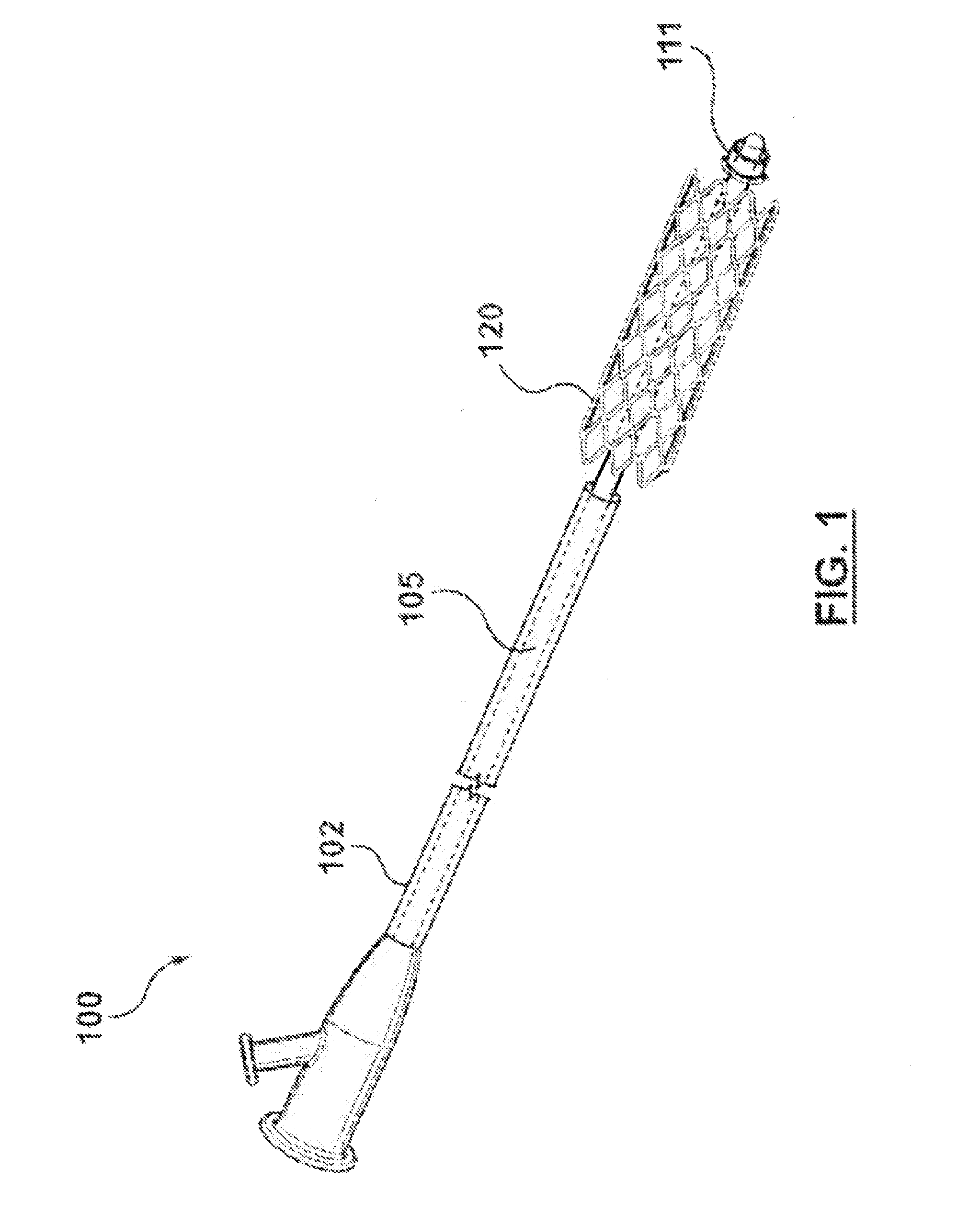
[0017]FIG. 1 is a perspective view of a stent delivery system made in accordance with the invention. The stent delivery system 100 includes a catheter 105, a sheath 102 disposed around the catheter 105, and a stent 120 disposed on the catheter 105. In this embodiment, the stent 120 is a self-expanding stent. FIG. 1 illustrates the stent delivery system 100 with the stent 120 expanded and deployed after the sheath 102 has been retracted or the catheter 105 has been advanced. Before the stent 120 is deployed, the stent 120 is disposed on the catheter 105 within the sheath 102. The stent 120 is operable for use in a vessel having a vessel wall forming a vessel lumen. The stent 120 is a welded stent in which one or more struts interconnect to form a tubular body. In one embodiment, the stent delivery system 100 can include retention means 111, such as mechanical or adhesive structures, for retaining the stent 120 on the catheter 105 until the stent 120 is deployed.

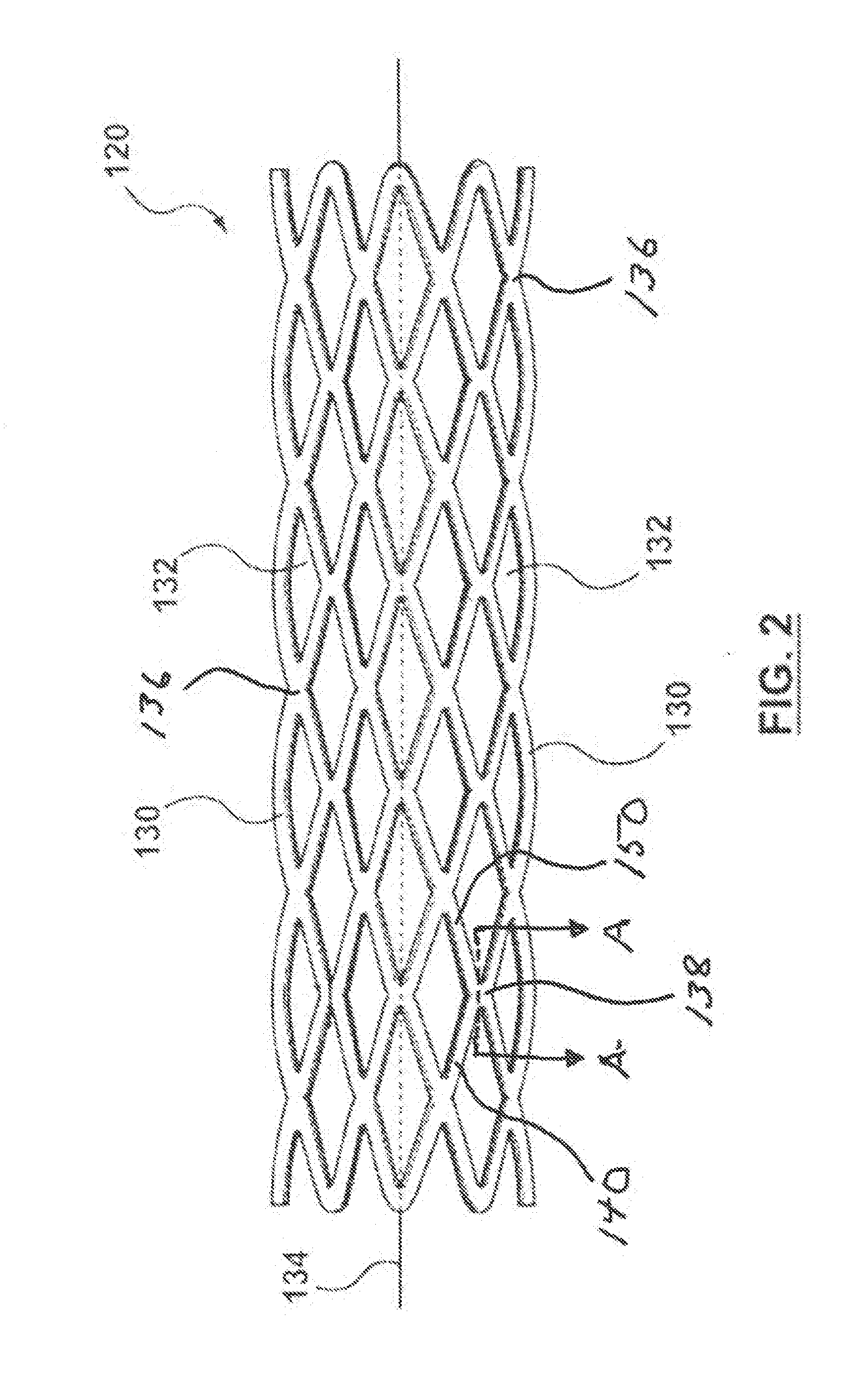
[0018]FIG. 2 is a side...


PUM

PropertyMeasurementUnit
Solubility (mass)aaaaaaaaaa

Abstract

A welded stent and stent delivery system, with a stent including a first strut having a first strut nickel titanium alloy layer and nickel titanium soluble core, the first strut nickel titanium alloy layer being disposed around the first strut nickel titanium soluble core; and a second strut having a second strut nickel titanium alloy layer and nickel titanium soluble core, the second strut nickel titanium alloy layer being disposed around the second strut nickel titanium soluble core, the second strut nickel titanium alloy layer being connected to the first strut nickel titanium alloy layer with a weld. The first and second strut nickel titanium alloy layers are made of a nickel titanium alloy, the first and second strut nickel titanium soluble cores are made of a nickel titanium soluble material, and the weld is made of an alloy of the nickel titanium alloy and the nickel titanium soluble material.

Description

TECHNICAL FIELD[0001]The technical field of this disclosure is medical implant devices, particularly, welded stents and stent delivery systems.BACKGROUND OF THE INVENTION[0002]Stents are generally cylindrical shaped devices that are radially expandable to hold open a segment of a blood vessel or other anatomical lumen after implantation into the body lumen. Stents have been developed with coatings to deliver drugs or other therapeutic agents.[0003]Stents are used in conjunction with balloon catheters in a variety of medical therapeutic applications including intravascular angioplasty. For example, a balloon catheter device is inflated during PTCA (percutaneous transluminal coronary angioplasty) to dilate a stenotic blood vessel. The stenosis may be the result of a lesion such as a plaque or thrombus. After inflation, the pressurized balloon exerts a compressive force on the lesion thereby increasing the inner diameter of the affected vessel. The increased interior vessel diameter fa...

Claims


Application Information

Patent Timeline
IPC IPC(8): A61F2/86A61F2/95
CPCA61F2/95A61F2/86A61F2/966A61F2220/0058A61F2240/001A61F2250/0031A61L31/022A61L31/148A61F2002/825B23K9/007B23K11/11B23K26/22B23K31/02
Inventor THOMPSON, DUSTIN
Owner MEDTRONIC VASCULAR INC
Why Eureka
Try Eureka