However, the hovering time as increased in this way is rather limited, usually a fighter can only take off with half load, and the engine is in the state of thrust augmentation at the time of take-off, thus shortening the aircraft's service life.
The aircraft carriers in Russia, England, Italy, Spain, India and other countries do not have qualified steam ejections yet due to the technology limitation, thus they can only adopt ski jump take-off.
The take-off weight and take-off efficiency of the ski jump take-off are less than that of the ejection take-off, and the combat efficiency thereof is poor than that of the steam
catapult.
(1) the required ejection force is large, and more work has to be done; the large ejection force is because that the aircraft stops on the take-off line when being ejected, thus in order to achieve high speed from static state, the
catapult needs to apply a force up to hundreds of tons; more work to be done is because of the large ejection force and the long journey of doing work (W=F*S), the
catapult needs to continue pushing the carrier aircraft to glide at an acceleration for a
stroke of about 100 m;
(2) the structure of the catapult is bulky, with a length up to 100 meters (the whole
stroke range), which takes much more space in the
hull of the aircraft carrier;
(3) the
pilot becomes stunned and very uncomfortable at the moment of ejection take-off because of high overload (e.g., 5.8 G);
(4) the
energy consumption is large; a steam catapult will usually consume 614 kilograms of steam for one ejection operation; a medium-sized fighter consumes about 1.5-2 tons of
fresh water for one ejection; to boil the
fresh water into steam also has to consume a huge amount of energy;
(5) the
fresh water consumption is large, thereby requiring larger scale self-made fresh water device, water tank, steam gas
storage tank and catapult pipeline box, etc., which need to take up more space;
(6) this kind of catapult equipment and auxiliary device with strict seal requirement, high
machining accuracy, difficult construction technology and high cost occupy vast space, which not only results in relatively difficult maintenance and usage in normal time, but also is easy to be damaged and hard to be repaired in time of war as a bulky weak part;
In addition, steam catapult has low efficiency, generally between 4% and 6%.
(1) the required ejection force is large, and more work has to be done; the catapult applies force on a carrier aircraft stopped on the take-off line in order to make it reach a high speed, thus the required ejection force is large; more work to be done is because of a large ejection force and a long journey of doing work (W=F*S), the catapult needs to continue to push the carrier aircraft to glide at an acceleration for a
stroke of about 100 m;
(2) the catapult structure is bulky and rather complex for it has 4 parts including a
linear induction motor of about 100 meters long (the horizontal ejection stroke is about 100 meters long), a high-power
electric control equipment, a forcing storage device and a power electronic transformation system, which occupy a lot of space in the
hull of the aircraft carrier and a large part of the
tonnage;
(4) the cost for development is expensive; the “Ford” aircraft carrier being constructed in the U.S. is not only expensive, but also too huge in the volume, thus the probability of being hit during the war will be increased accordingly, hence is easy to be damaged and difficult to be repaired;
But in the technology solution, the tackle mechanism is not described in details, unavoidably bringing about various uncertainty and difficulty for implementation of the project technology; Especially, there is no specific restriction on the airborne engine, in the discussion of theoretical basis in practice, the aircraft engine is taken as an example, while research and development on specialized
aviation engine faces great challenges of
heavy weight, huge volume, and
adaptation between tackle and carrier aircraft, as well as braking at the bow, which have become the difficulties of
engineering technology application.
1) short on-
deck runway; aircraft carrier is limited in length, and the section for the carrier aircraft to land is more limited, while the length of landing area on the aircraft carrier is relevant to the safety in landing of the carrier aircraft;
2) high landing speed; in the existing technology, when directly gliding to touch down onto the carrier, the aircraft shall not
throttle back to decelerate, but requires a force appropriately, so that it can immediately go around in case the arresting cable is missing hooked (the statistics of carrier aircraft training shows that, among the four states of safe landing, going around, escaping and crashing into the aircraft, the “going around” is of the largest probability being 40%-50%);
3) the accuracy requirement for predetermined
landing point is strict; for the accuracy of the
landing point, none of longitudinal, lateral and height errors can be large, otherwise the aircraft may not hook the arresting cable, or may land on the aft or on the right side of the carrier bridge etc., while the carrier aircraft needs to, during gliding at high speed, finish “hitting” the landing position on the
deck of the aircraft carrier being moving;
4) control of the gliding angle; generally, a glide angle of 3˜3.5° (3.5˜4°) is preferred; This angle is critical for “the probability of ‘hitting’ the deck”, an angle that is too large will increase the
impact on the aircraft, and an angle that is too small will extend the gliding distance. However a glide trace of the carrier aircraft always has a certain deviation from the correct glide curve, which may often present a fluctuation of changes in the curve;
5) alignment with the center line of the
runway; in a sense, an alignment is more important than the gliding angle; the runway of the aircraft carrier is very narrow, thus if the aircraft deviates to right, it may hit the
superstructure (carrier bridge) of the aircraft carrier, and if the aircraft deviates to left, it may hit other aircraft on the parking apron. So during the landing stage, the carrier aircraft should fly (glide) in a
vertical plane where the center line of the landing runway is located; however the center line of the canted deck runway used for landing is not consistent with the heading direction of the aircraft carriers, but presenting an angle of 6˜13° (namely the canted deck and the longitudinal axis of the aircraft carrier form an angle of 6˜13°); this design aims to allow a carrier aircraft rolling after landing so as to avoid other carrier aircrafts which are waiting for take-off at the front part of the carrier, but it also put the carrier aircraft in the course of gliding down to trouble; in order to catch up with the aircraft carrier from behind and fly at a high speed by keeping the same direction with that of the aircraft carrier, it is impossible for the aircraft to fly (gliding down) in the
vertical plane where the center line of the canted deck runway, forming an angle of 6˜13° with the heading direction of the aircraft carrier, is located, since when the aircraft is just about to obliquely travel along the direction which forms an angle of 6˜13° with the longitudinal axis of the aircraft carrier, the
vertical plane passing through the center line of the canted deck runway has already horizontally moved to right forward; no wonder the American pilots always complain that the canted deck is “escaping from” the landing aircraft.
2. Current Vertical Landing Technology for the Aircraft on an Aircraft Carrier
Since during the vertical landing, the aircraft does not have a level speed, no wing lift is available; it is required to use the vector propulsion technology to produce a great, vertical upward force to “support” the aircraft “hovering” in the air for slow landing, the source of force is the power of the carrier aircraft itself which consumes a lot of airborne fuel.
After consumption for vertical take-off, the airborne fuel has been no longer sufficient, and it is still necessary to reserve a large amount of oil to prepare for landing, thus the quantity of bombs carried by the aircraft and the voyage will be inevitably restricted.
Moreover, other supporting aircrafts such as
attack aircraft and early warning aircraft on the aircraft carrier will not adopt vector propulsion technology, since it's not suitable for vertical take-off and landing.
So the vertical take-off and landing technology is not able to smooth over the problems faced by the existing take-off and landing system of the carrier aircraft yet.
This may relate to the needs for electromagnetic silent during the war to eliminate the possibility of occurrence of
electromagnetic interference,
electronic warfare and so on, and more relevant to the difficulty, accuracy of measurement, acquisition and
processing of parameters required by the
computing center: both the aircraft carrier and the carrier aircraft are in movement with complex relative motions there-between, and the sea is short of landmarks, thus the required
flight data acquisition is not comprehensive enough and less precise, and it is also difficult to process the data.
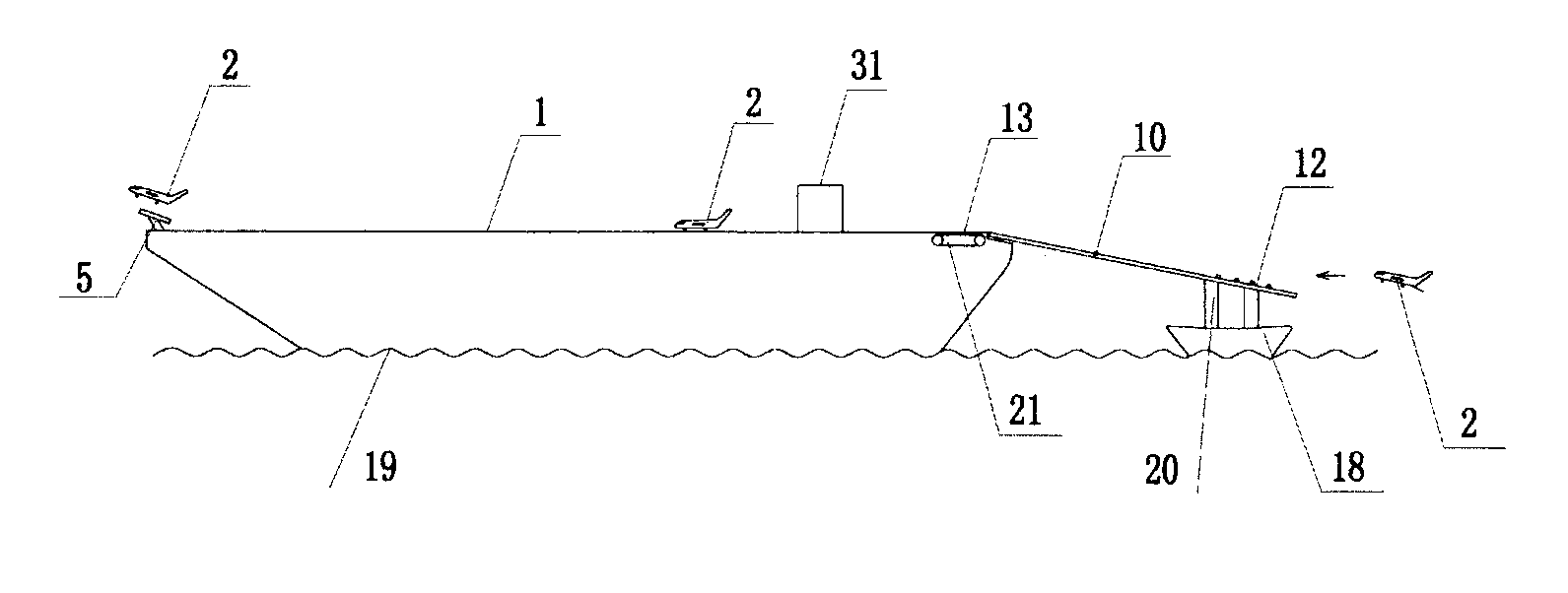
However, said runway for the carrier aircraft extending out of the aircraft carrier body in the solution is basically kept a level same with the sea surface, while the flight deck on the aircraft carrier is about 20 meters high above the
sea level, thus it is quite difficult to support the runway extending out of the carrier body to such a height by means of a floating boat and several temporary floaters, technically; moreover, to keep it in the level state may not necessarily be most beneficial for landing on the aircraft carrier; additionally, there is no specific descriptions in the solution about perfect anti-shaking preventive measures of a on-deck runway extending out of the carrier for resisting longitudinal, lateral shaking of the aircraft carrier in the sea, wave influence or about cooperation with other aid, braking mechanisms, etc.
He unfortunately lost his life in a landing accident and the aircraft was destroyed, resulting in the carrier aircraft, for a while, landing in the nearby sea surface as a change.
As the flight deck of an offshore platform for take off and landing system of the aircraft carrier, apart from the obviously most essential problem of a
short length, there are of course other problems for
layout and feasibility, as described below.
According to the present technology, in order to extend the flight deck, it is forced to increase the displacement of the aircraft carrier, which is accompanied by cost rise and inconvenience in driving and berthing.
If the
tonnage is further increased, it will do more harm than good.
2. When the carrier aircraft is landing, it is difficult to align with a center line of the canted deck runway of the aircraft carrier.
It is not easy to fly and glide down to land in the vertical plane where this center line of canted deck runway is located.
The problem also lies in that a flight deck is not long enough.

