Color filter for organic electroluminescence display device, and organic electroluminescence display device

a display device and color filter technology, applied in thermoelectric devices, optical elements, instruments, etc., can solve the problems of uneven brightness of the screen, difficult to prevent a leakage of light completely, constant consumption of electric power of the display, etc., to reduce the risk of cost, the effect of preventing the generation of brightness unevenness

Active Publication Date: 2014-09-25
DAI NIPPON PRINTING CO LTD
View PDF4 Cites 33 Cited by
  • Summary
  • Abstract
  • Description
  • Claims
  • Application Information

AI Technical Summary

Benefits of technology

[0039]The color filter of the present invention is configured to have a transparent substrate, a colored layer that is a pixel region formed on the transparent substrate, a non-pixel area formed around the colored layer, in which a convex pillar is formed in at least one spot of the non-pixel area, and an auxiliary electrode layer is present on a top and a side of the convex pillar, and on the non-pixel area. Thus, when the color filter is used to constitute an organic EL display device having a large screen, the generation of brightness unevenness can be prevented between the central region of the screen and the outer circumferential regi

Problems solved by technology

Moreover, in the light-receiving type display, such as a liquid crystal display (LCD), a backlight is constantly lighted in spite of the manner of information displayed thereon, so that the display constantly consumes an electric power not different from that consumed in a full-display state.
Similarly, liquid crystal displays (LCDs) block light from their backlight source to gain a dark state; thus, even when the light is small in quantity, it is difficult that a leakage of the light is complet

Method used


Image

  • Color filter for organic electroluminescence display device, and organic electroluminescence display device
  • Color filter for organic electroluminescence display device, and organic electroluminescence display device
  • Color filter for organic electroluminescence display device, and organic electroluminescence display device

Examples


first embodiment

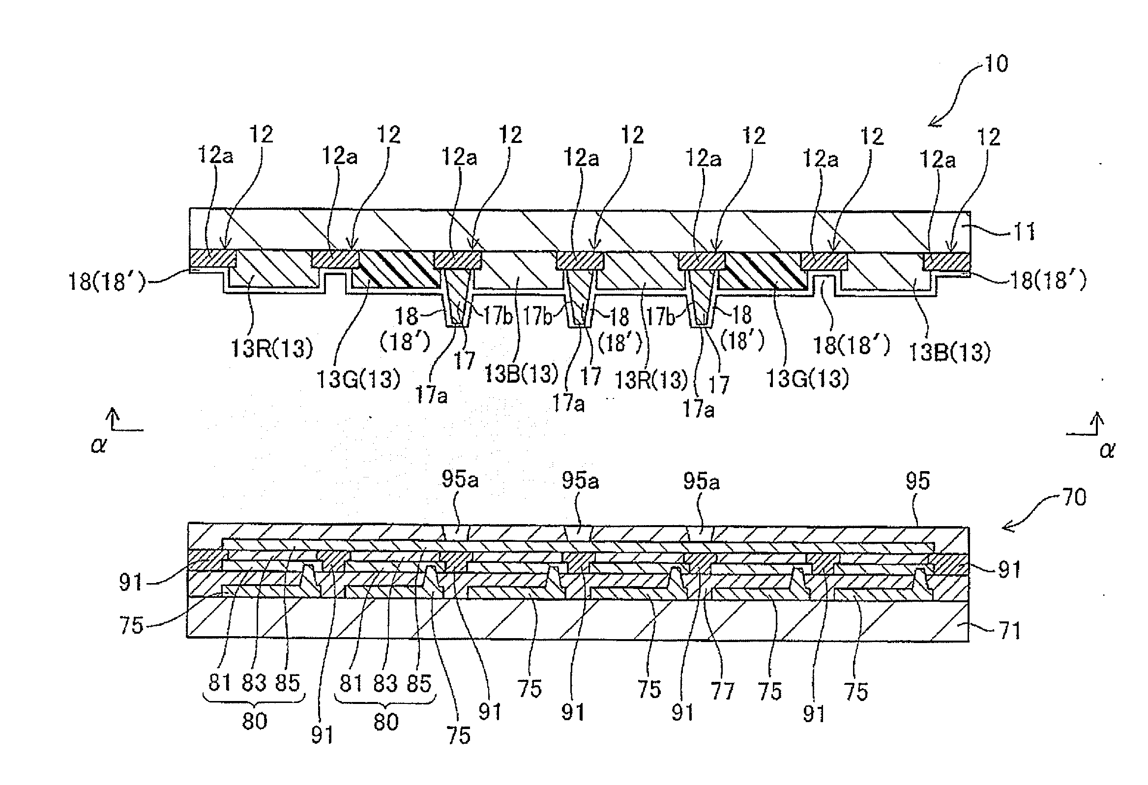
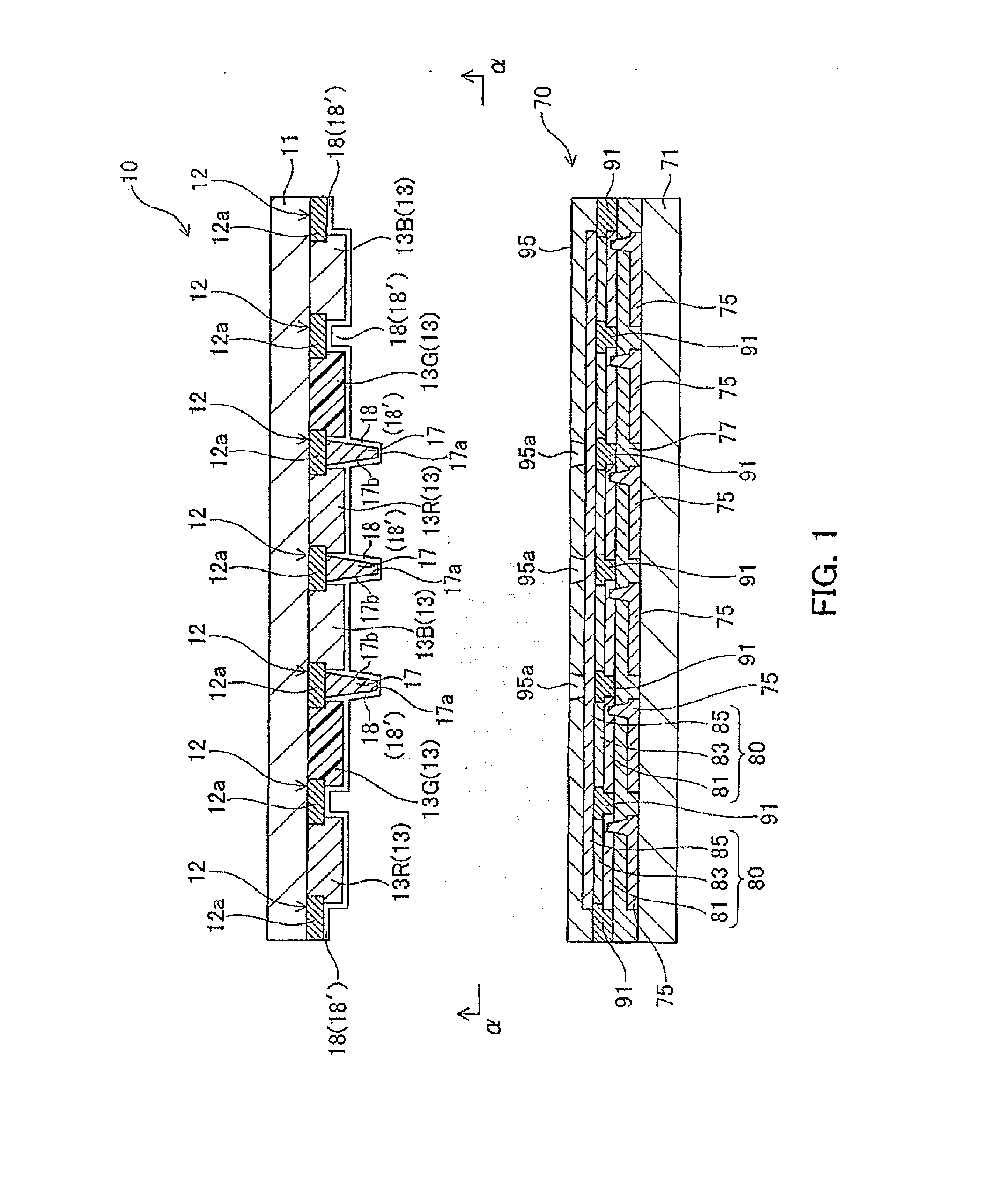
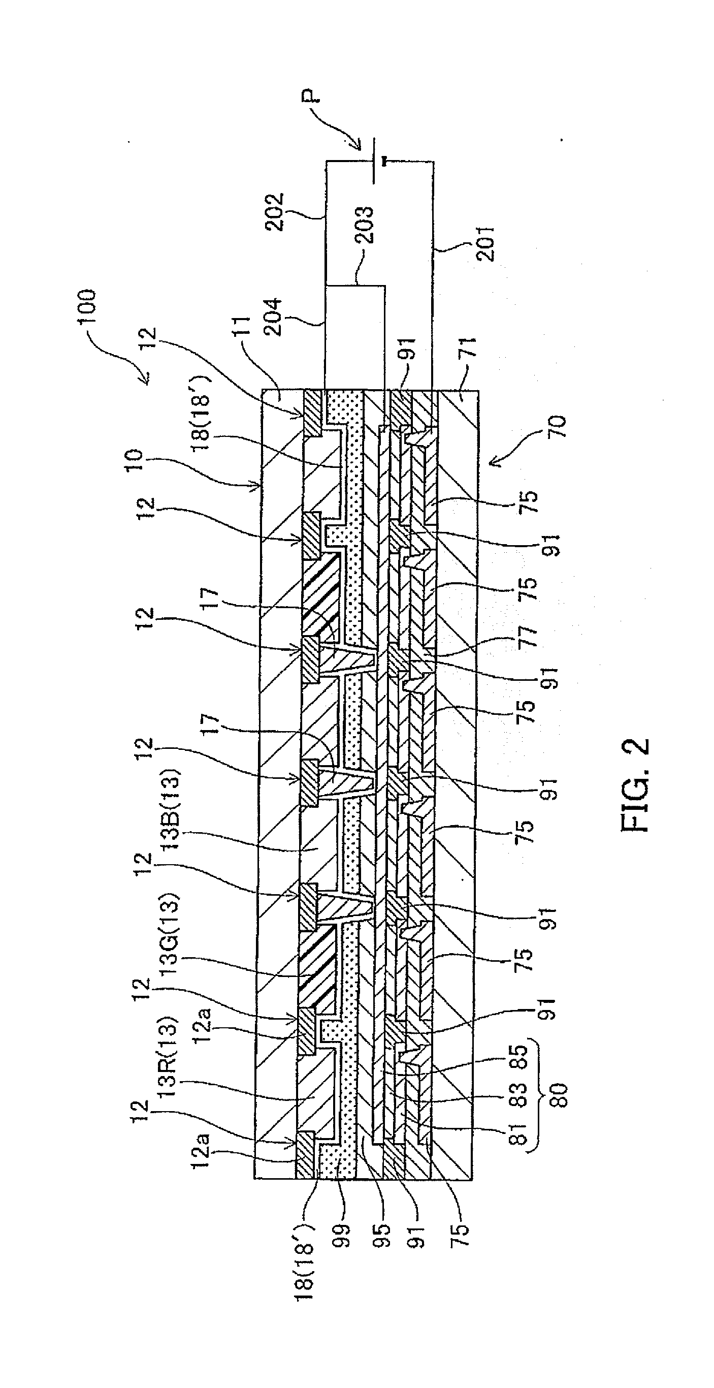
[0058]Referring to FIGS. 1 to 3, a description will be made about a color filter for organic EL display device, and an organic EL display device according to a first embodiment of the present invention.

[0059]FIG. 1 is a sectional view illustrating the color filter of the invention for organic EL display device, which is a filter 10, and an organic-EL-element-side substrate 70. This sectional view, which is a sectional view of structural members of the filter and the substrate, is a sectional view illustrating a cut surface of the color filter 10 illustrated in FIG. 3 for organic electroluminescence display device along line A-B-C-D-E-F-G-H-I-J-K-L-M-N in this plan view, and a cut surface, which is similar thereto, of the organic-EL-element-side substrate 70. FIG. 2 is a sectional view of the organic EL display device, which is a display device 100, formed by joining the color filter 10 for organic EL display device and the organic-EL-element-side substrate 70, which are illustrated ...

second embodiment

[0136]Referring to FIGS. 4 to 6, a description will be made about a color filter for organic EL display device, and an organic EL display device according to a second embodiment of the present invention.

[0137]FIG. 4 is a sectional view illustrating the color filter of the invention for organic EL display device, which is a filter 20, and an organic-EL-element-side substrate 70. This sectional view, which is a sectional view of structural members of the filter and the substrate, is a sectional view illustrating a cut surface of the color filter 20 illustrated in FIG. 6 for organic electroluminescence display device along line A-B-C-D-E-F-G-H-I-J-K-L-M-N in this plan view, and a cut surface, which is similar thereto, of the organic-EL-element-side substrate 70. FIG. 5 is a sectional view of the organic EL display device, which is a display device 100, formed by joining the color filter 20 for organic EL display device and the organic-EL-element-side substrate 70, which are illustrated...

third embodiment

[0143]Referring to FIGS. 7 to 9, a description will be made about a color filter for organic EL display device, and an organic EL display device according to a third embodiment of the present invention.

[0144]FIG. 7 is a sectional view illustrating the color filter of the invention for organic EL display device, which is a filter 30, and an organic-EL-element-side substrate 70. This sectional view, which is a sectional view of structural members of the filter and the substrate, is a sectional view illustrating a cut surface of the color filter 30 illustrated in FIG. 9 for organic electroluminescence display device along line A-B-C-D-E-F-G-H-I-J-K-L-M-N in this plan view, and a cut surface, which is similar thereto, of the organic-EL-element-side substrate 70. FIG. 8 is a sectional view of the organic EL display device, which is a display device 100, formed by joining the color filter 30 for organic EL display device and the organic-EL-element-side substrate 70, which are illustrated ...


PUM


Abstract

When a large-screen organic EL display device is developed, the generation of a brightness unevenness is prevented between its screen central region and its screen outer circumferential region. Cost risk is decreased about the formation of a structure of preventing the generation of the brightness unevenness. Furthermore, an original protecting function for its organic EL elements is maintained. The color filter of the present invention comprises a transparent substrate, a colored layer that is a pixel region formed on the transparent substrate, and a non-pixel area formed around the colored layer, wherein a convex pillar is formed in at least one spot of the non-pixel area, and an auxiliary electrode layer on a top and a side of the convex pillar, and on the non-pixel area.

Description

TECHNICAL FIELD[0001]The present invention relates to a color filter used in an organic electroluminescence (also referred to as “organic EL” hereinafter) display device, and an organic EL display device formed to have this filter.BACKGROUND ART[0002]In recent years, flat-panel displays have been used in many fields and places, and the importance thereof has been increasingly becoming higher while informatization has been advancing.[0003]It is said that the current major presence of flat-panel displays is liquid crystal displays (LCDs). Active developments have been made also about flat-panel displays based on a display principle different from that of liquid crystal displays (LCDs), such as organic ELs, inorganic ELs, plasma display panels (PDPs), light emitting diode display devices (LEDs), vacuum fluorescent display devices (VFDs), and field emission displays (FEDs).[0004]These new flat-panel displays are each called a self-luminous type display. The displays are largely differen...

Claims


Application Information

Patent Timeline
IPC IPC(8): H01L27/32H01L51/52G02B5/20
CPCH01L27/322H01L51/52G02B5/20H05B33/26G02B5/201G02B5/223G02B2207/113H10K59/38H10K59/122H10K59/131H10K50/80
Inventor NAKAZAWA, SHINSUKEHINO, KAZUYUKI
Owner DAI NIPPON PRINTING CO LTD
Why Eureka
Try Eureka