Sulfur removal methods

a technology of sulphur removal and fluid, applied in the direction of sulfur preparation/purification, sulfur compounds, separation processes, etc., can solve the problems of reducing sulphur recovery efficiency, reducing sulphur quality, and reducing the fouling/deactivation of catalysts, so as to prevent fouling or deactivation of catalysts

Active Publication Date: 2014-10-02
MESSER IND USA INC
View PDF4 Cites 4 Cited by
  • Summary
  • Abstract
  • Description
  • Claims
  • Application Information

AI Technical Summary

Benefits of technology

[0040]As an advantage of the present invention the conversion of ammonia to nitrogen at the reaction temperature prevents the formation of solid ammonia salts at cold spots of Claus section down-stream of the Claus furnace.
[0041]As another advantage of the present invention, thorough oxidation of the hydrocarbon prevents the fouling or deactivation of the catalyst described above.
[0042]According to an embodiment of the present invention, the...

Problems solved by technology

A breakthrough of hydrocarbons leads to catalyst fouling/deactivation and reduced sulphur quality.
Even more sensitive to reduced furnace temperature is the efficiency of NH3 destruction. if the latter is incomplete NH3 buil...

Method used


Image

  • Sulfur removal methods
  • Sulfur removal methods
  • Sulfur removal methods

Examples


example 1

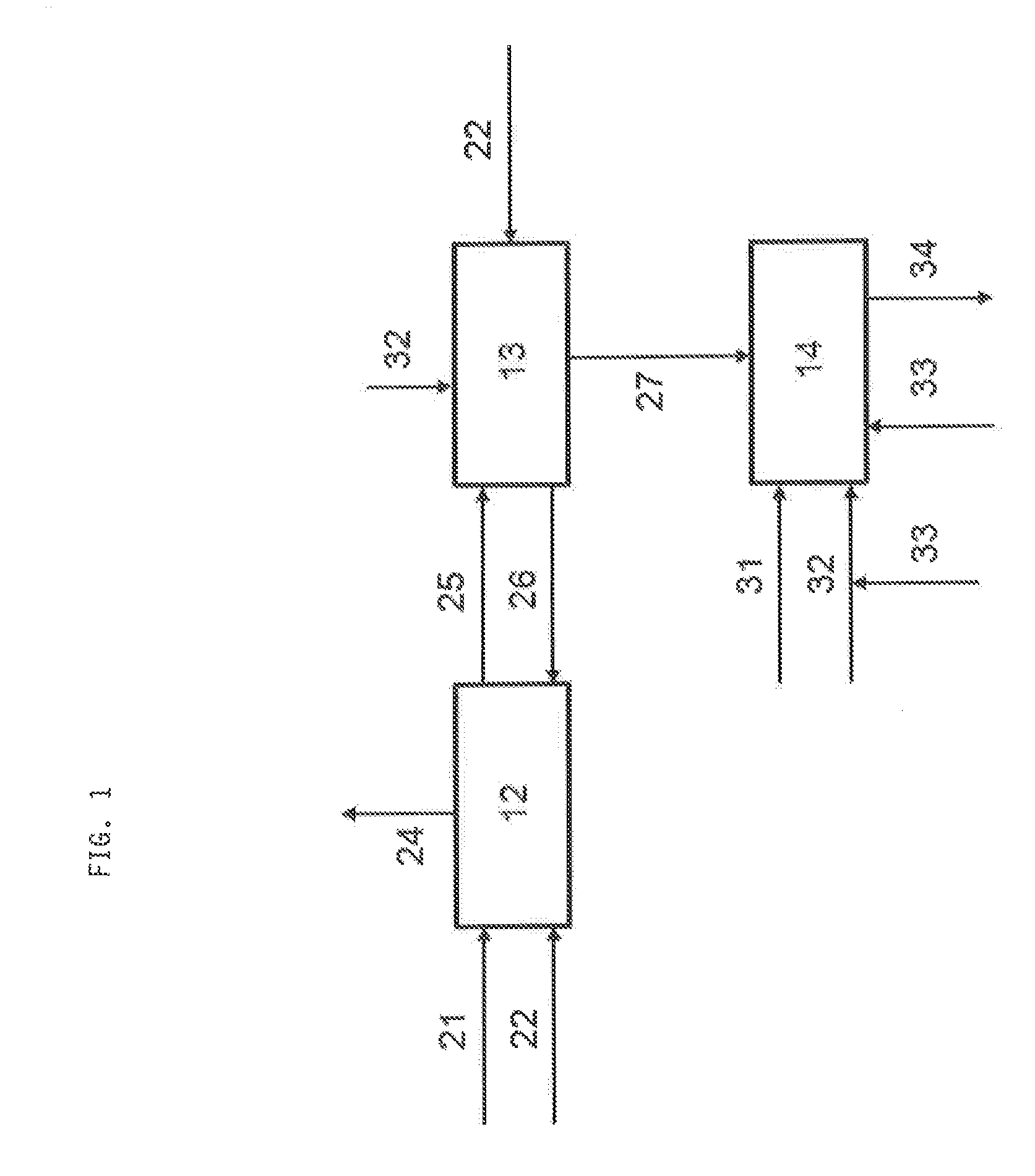
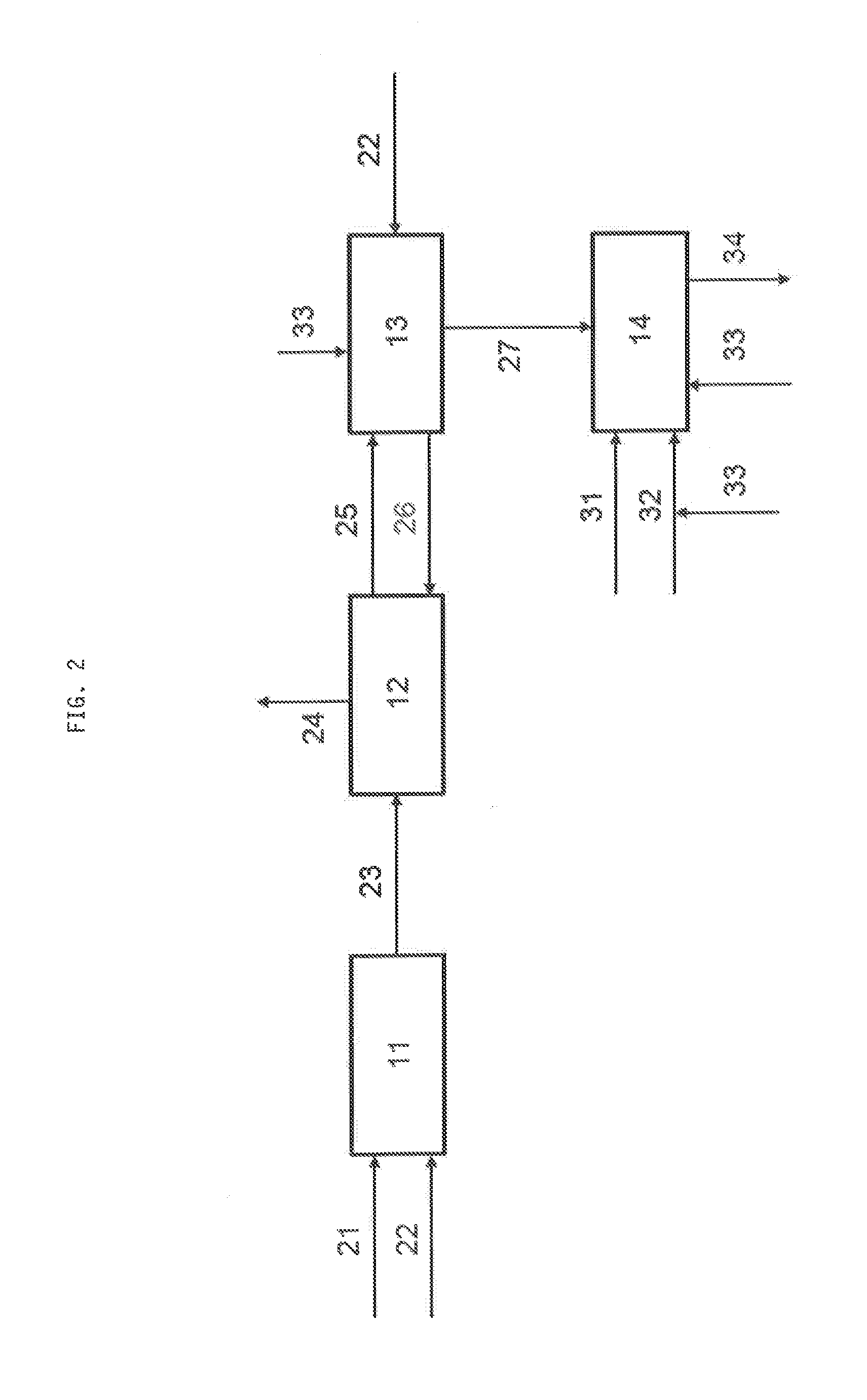
[0048]In oil refineries a new process for deep desulphurisation of hydrocarbon streams 21 containing S-bearing molecules made its entrance within the last years. This process (also denoted as S-Zorb), based on reductive adsorption 12 of sulphur on a solid 26, leads—by oxidative regeneration 13 of the loaded adsorbent 25 by air 32 oxidation—to an off-gas 27 comprising an appreciable but not dominating amount of SO2 (e.g. 5 vol.-%). A detailed description of said S-Zorb process can be found in Song et al., Applied Catalysis B: Environmental 41 (2003), pages 207-238.

[0049]One way of getting rid of this waste stream 27 is to send it into a Claus unit (or Claus process) 14, wherein all the components of this waste stream are present (N2, O2, CO, CO2, arenes, hydrocarbons) respectively are produced within the Claus furnace (SO2, H2, CO, CO2).

[0050]In case above mentioned waste stream is fed into the Claus unit 14 it has to be assumed that the temperature in the Claus furnace may drop cons...

example 2

[0062]This concept not only holds for waste streams coming from the S-Zorb process mostly applied within oil refineries. For gasification schemes an adsorptive process is already highly developed in order to realize hot gas desulphurisation. Here, also a waste gas is produced in the adsorbent regeneration step, which can be sent into a Claus unit. Here, again, the combination with oxygen application is an elegant solution; getting rid of SO2 by recovering the sulphur. Also the sulphur removal of other gas streams such as natural gas is a source for sulphur dioxide rich waste streams, which can be processed as described above.

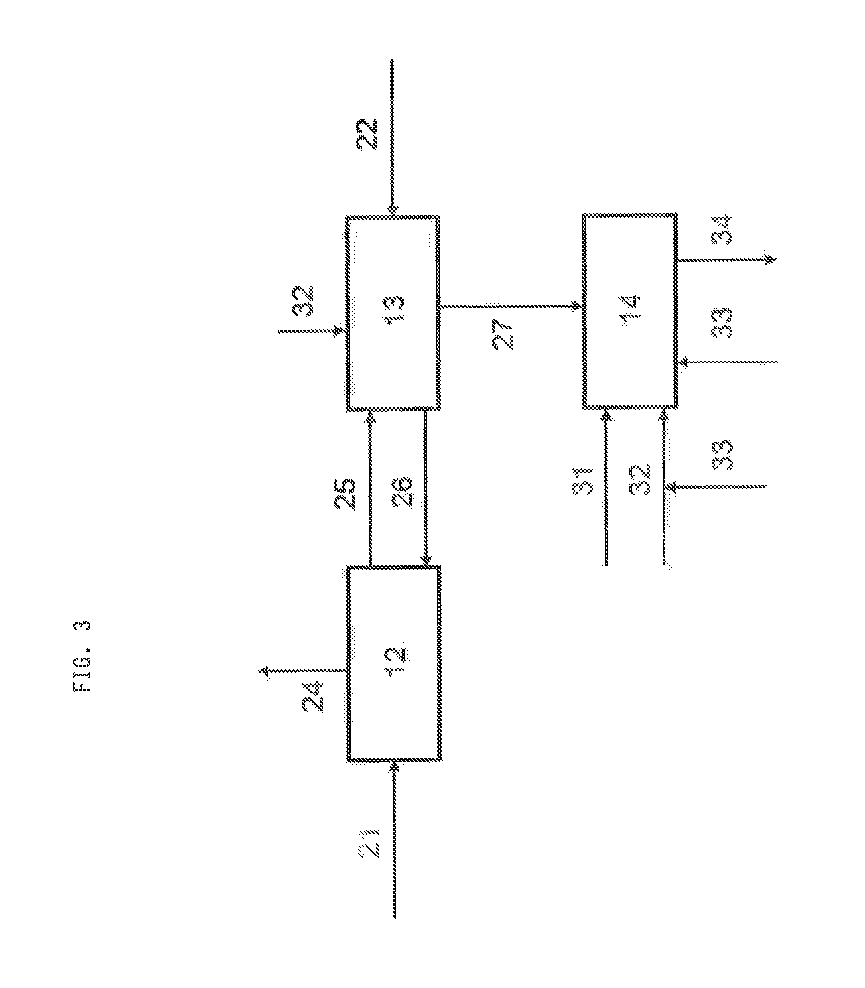
[0063]In case of a hydrocarbon stream such as natural gas or another gas stream such as raw synthesis gas already comprises hydrogen sulphide, the stream (21) is directly contacted with the adsorbent (FIG. 3) without any work-up. Again, adsorption 12, regeneration 13 and feeding the resulting off-gas stream 27 to the Claus unit 14 is performed analogously to the...


PUM

PropertyMeasurementUnit
Temperatureaaaaaaaaaa

Abstract

A method for removing sulphur from a fluid by the steps of providing a first fluid comprising a sulphur-containing compound; adsorbing the sulphur of sulphur-containing compound onto an adsorbent; regenerating the adsorbent by oxidation of the adsorbed sulphur to sulphur dioxide thereby yielding an off-gas stream comprising sulphur dioxide; providing a second fluid comprising hydrogen sulphide, using the second fluid and the off-gas stream as reactants in a Claus process for producing elemental sulphur, wherein a part of hydrogen sulphide provided by the second fluid is oxidized to sulphur dioxide and water at reaction temperature, the residual hydrogen sulphide, the resulting sulphur oxide and the sulphur oxide provided by the off-gas stream are converted to elemental sulphur, the oxygen required for the oxidation of the hydrogen sulphide provided by the second fluid is provided by an air stream, and the off-gas stream dilutes the second fluid in the Claus process.

Description

CROSS-REFERENCE TO RELATED APPLICATIONS[0001]This application claims priority from European Patent Application 13001642.1 filed Mar. 28, 2013.BACKGROUND OF THE INVENTION[0002]The present invention relates to a method for removing sulphur from a fluid.[0003]Such a method comprises the steps of providing a first fluid comprising a sulphur-containing compound, adsorbing the sulphur of the sulphur-containing compound onto an adsorbent, particularly in the presence of hydrogen, regenerating the adsorbent by oxidation of the adsorbed sulphur to sulphur dioxide thereby yielding an off-gas stream comprising sulphur dioxide, providing a second fluid comprising hydrogen sulphide, using the second fluid and the off-gas stream as reactants in a Claus process for producing elemental sulphur, wherein a part of hydrogen sulphide provided by the second fluid is oxidized to sulphur dioxide and water at an reaction temperature, and wherein the residual hydrogen sulphide, the resulting sulphur oxide a...

Claims


Application Information

Patent Timeline
IPC IPC(8): C01B17/05C01B17/04
CPCC01B17/0447C01B17/05B01D53/04B01D53/52B01D2257/304C01B17/0413B01D2251/602B01D2253/1124C01B17/0408C10G25/003C10G45/08B01D53/48C01B17/04
Inventor SCHREINER, BERNHARD
Owner MESSER IND USA INC
Why Eureka
Try Eureka