Composite metal surface

Active Publication Date: 2014-10-02
PHILIPS IP VENTURES BV
View PDF2 Cites 11 Cited by
  • Summary
  • Abstract
  • Description
  • Claims
  • Application Information

AI Technical Summary

Benefits of technology

The patent describes a method to make a composite metal surface that looks metallic and has good permeability and conductivity. The method involves combining metal powder and binder in a specific ratio to insulate the metal particles from each other and reduce conductivity. The composite metal surface can also be made with multiple layers that have different properties, such as higher bulk conductivity in the outer layers for improved appearance. The method involves molding the mixture in a pressure press and curing it to create the composite metal surface. Overall, the invention provides a way to create a metallic-looking surface with good permeability and conductivity.

Problems solved by technology

During manufacture, the binder insulates the aluminum powder particles from each other thereby reducing the bulk conductivity of the resultant composite metal surface.
In addition, the sieving can affect the resultant look of the composite metal surface including how metallic the surface looks.

Method used


Image

  • Composite metal surface
  • Composite metal surface
  • Composite metal surface

Examples


Embodiment Construction

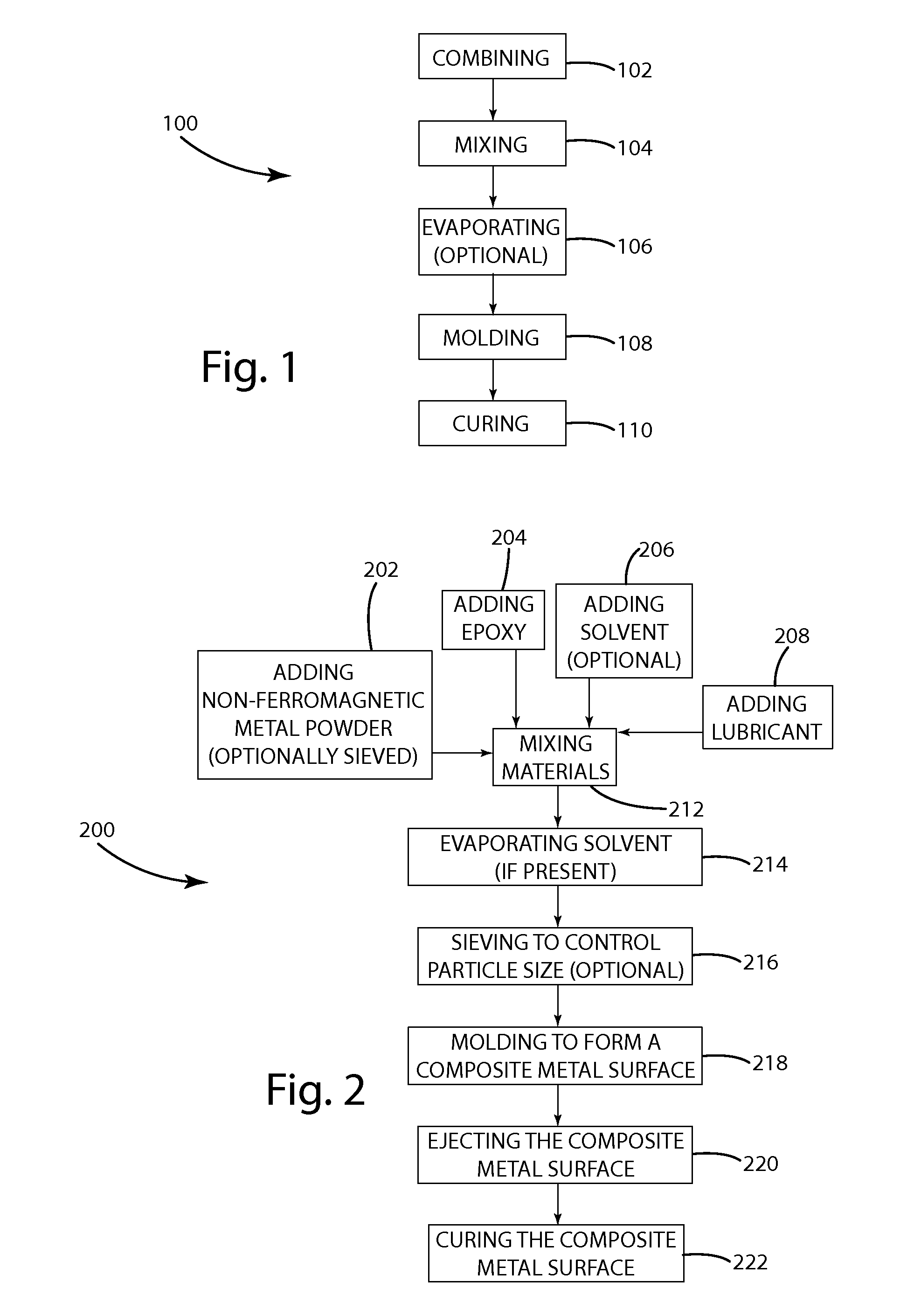
[0047]A flowchart for a method for manufacturing a composite metal surface in accordance with an embodiment of the present invention is illustrated in FIG. 1 and generally designated 100. The method 100 generally includes the steps of 1) combining 102 metal powder (in this embodiment aluminum powder), binder, solvent (optionally), and lubricant (optionally); 2) mixing 104 at least the aluminum powder, binder, solvent, and lubricant to create a mixture; 3) evaporating 106 if the mixture includes a solvent, for example by heating and / or applying a vacuum to the mixture; 4) molding 108 the mixture to form a composite metal surface; and 5) curing 110 the composite metal surface at a temperature sufficient to cure the binder. Although the materials are all combined, the combination need not take place just before the mixing or at the same time. In some embodiments, the particle size of the mixture may be controlled before pouring the mixture into the mold cavity, for example by sieving. ...


PUM

PropertyMeasurementUnit
Electrical conductivityaaaaaaaaaa
Ratioaaaaaaaaaa
Permeabilityaaaaaaaaaa

Abstract

A composite metal surface that looks metallic, but permits effective transmission of an electromagnetic field. The composite metal surface can be integrated into various electronic equipment, such as telephones, remote controls, battery doors, keyboards, mice, game controllers, cameras, laptops, inductive power supplies, and essentially any other electronic equipment. The composite metal surface can also be integrated into non-electrically conductive heat sinks, high permeability shielding, and polished metal non-electrically conductive surfaces.

Description

BACKGROUND OF THE INVENTION[0001]Electronic equipment, such as cell phones and laptops, often is shielded to prevent unwanted exposure to electromagnetic radiation and to limit unwanted electromagnetic emission. However, an electromagnetic aperture is routinely provided in the shielding in order to pass electromagnetic fields between electronics located inside electronic equipment and the outside world.[0002]The electronic equipment market, especially the cellular telephone market, is competitive and manufacturers often compete to provide the most aesthetically pleasing device. An enormous amount of resources are spent in designing the look and feel of electronic devices. One common design constraint is the material used to cover the electromagnetic aperture, typically a non-metal material such as rubber or plastic. Unfortunately, the contrast of the non-metal electromagnetic aperture material to the metal shielding material can detract from the aesthetics of the electronic equipmen...

Claims


Application Information

Patent Timeline
IPC IPC(8): H05K9/00B32B15/04B22F7/00B32B5/30
CPCH05K9/0083B22F7/008B32B15/043B32B5/30C08L63/00H01B1/22Y10T428/12146Y10T428/12014
Inventor BAARMAN, DAVID W.MOES, BENJAMIN C.KUYVENHOVEN, NEIL W.SCHWANNECKE, JOSHUA K.TAYLOR, JR., ROY M.TURNER, KAITLYN J.WOLFORD, ROBERTNORCONK, MATTHEW J.SCHAMPER, RYAN D.
Owner PHILIPS IP VENTURES BV
Why Eureka
Try Eureka