Double layer transfer method

a transfer method and layer technology, applied in the field of double layer transfer method, can solve the problems of limiting the number of possible technologies, unable to find an intermediate bonding with a stronger binding energy, and unable to use the same bonding method for the initial substrate bonding (first step), so as to facilitate the debonding of the layer

Active Publication Date: 2014-10-02
COMMISSARIAT A LENERGIE ATOMIQUE ET AUX ENERGIES ALTERNATIVES
View PDF4 Cites 21 Cited by
  • Summary
  • Abstract
  • Description
  • Claims
  • Application Information

AI Technical Summary

Benefits of technology

[0016]Thus, the method according to the invention implements a double layer transfer such that technological steps may be carried out on the exposed or free rear face of the layer when the front face is bonded onto an intermediate substrate. Furthermore, during the double layer transfer, it is frequent to implement the steps of etching the substrate to be removed, leading to the loss of the substrate. The method according to the invention advantageously makes it possible to selectively detach or peel off (debond) the substrates to be removed such that it becomes possible to recycle them for reuse in the method.
[0049]In particular, the final bonding energy Ef between a rear face of the layer and the final substrate of the intermediate structure is higher than the intermediate bonding energy Ei2 between the front face of the layer and the intermediate substrate in an atmosphere having a humidity content ranging between 20 and 80%. Under these conditions, it is thus possible to debond the layer from the intermediate substrate.

Problems solved by technology

Yet, the order of the binding energies of these different bondings highly restricts the number of possible technologies for implementing the bonding of the layer on the different substrates and the selective debonding of the layer from these same substrates.
Particularly, it seems impossible to use the same method for the bonding of the layer onto the initial substrate (first step) and for the bonding of the layer and the final substrate (last step).
Indeed, if the same method or type of bonding is implemented in the first and last steps, which can be likened to bondings having a similar bonding energy, it does not seem possible to find an intermediate bonding with a binding energy stronger than the first bonding and at the same time lower than the last bonding.

Method used


Image

  • Double layer transfer method
  • Double layer transfer method
  • Double layer transfer method

Examples


Embodiment Construction

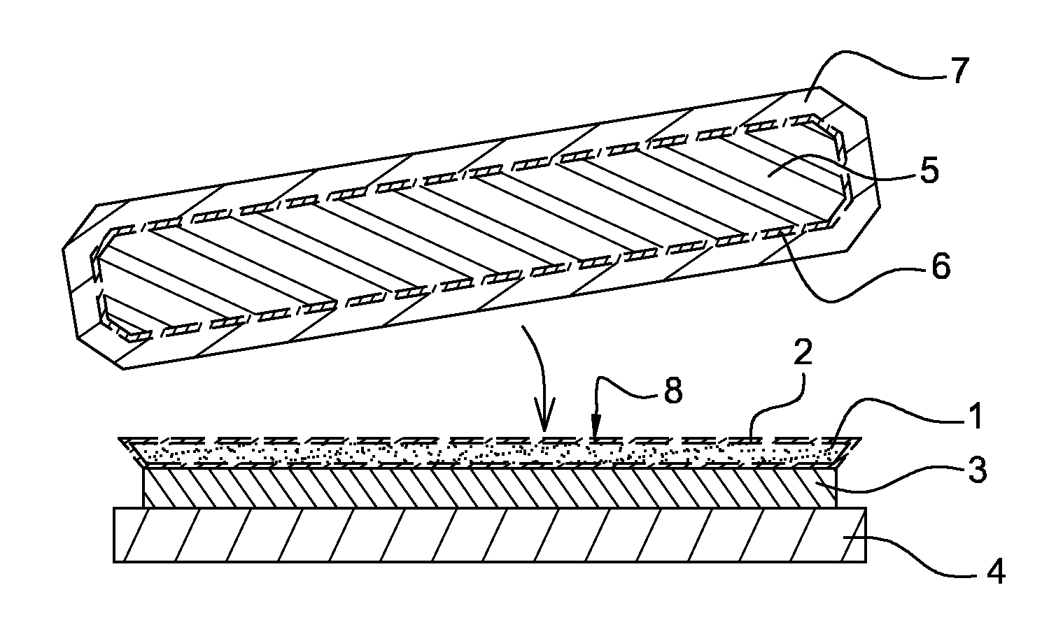
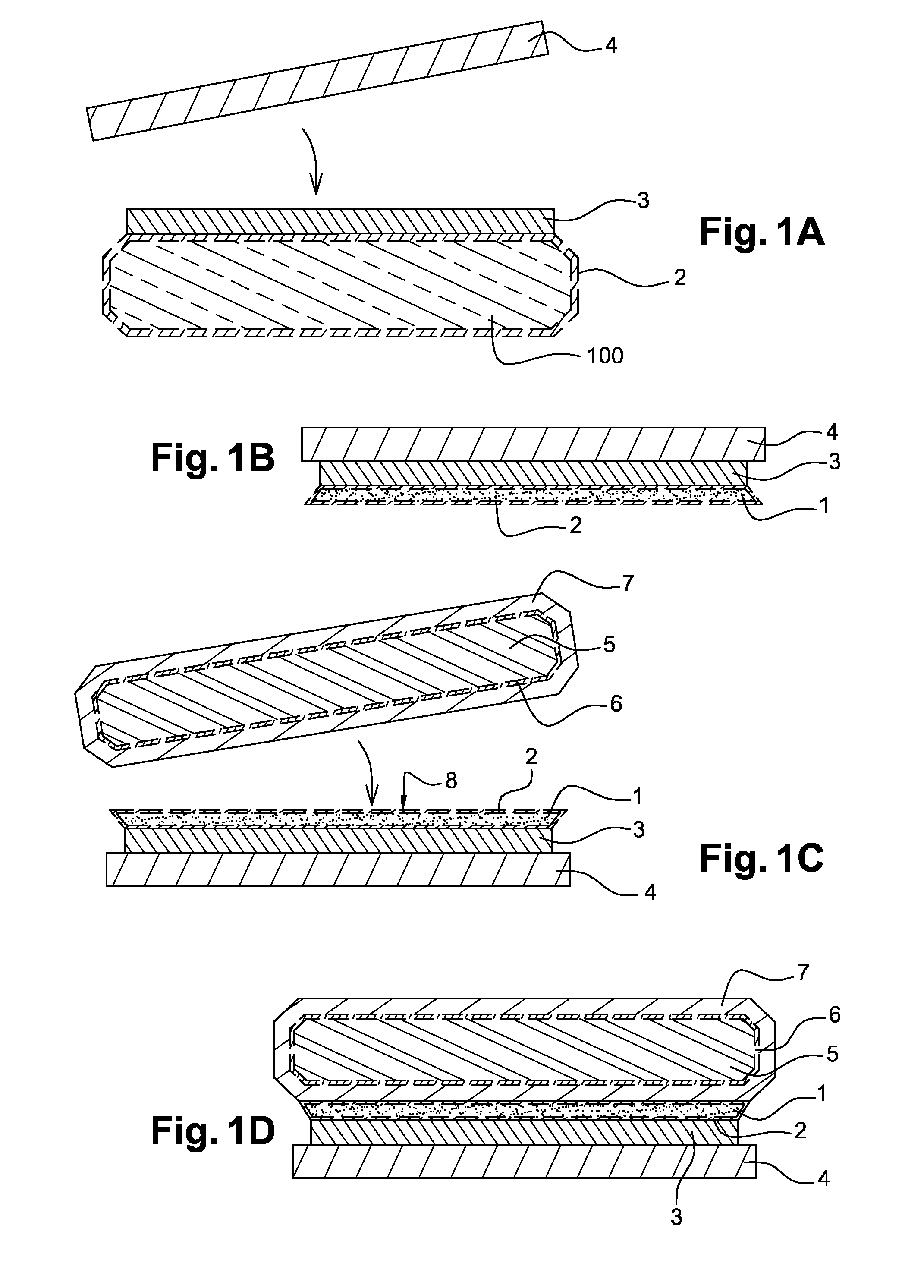
[0061]With reference to FIG. 1A, the method is implemented based on a silicon donor substrate 100 with a thickness of around 725 micrometers from which the layer 1 to be transferred will be prepared. Such a substrate 100 typically has fallen edges at the periphery of its surface that are made according to the SEMI standards. These fallen edges facilitate the handling of the substrate which would otherwise flake away and create particles at the surface, liable to hinder a subsequent bonding. A native oxide layer 2 is formed on the surface of the substrate 100 when in contact with air. An adhesive film 3 made of DVS-bis-BCB polymer is deposited on the silicon substrate 100, with a thickness of 10 micrometers by centrifugal coating or spin coating, a method well known by the skilled person. The DVS-bis-BCB film 3 is then cross-linked by applying a thermal treatment at 250° C. for 1 hour. A polymer substrate 4, for example a polyimide such as “Kapton®”, having a thickness higher than 50...


PUM


Abstract

A method of transferring a layer including: a) providing a layer joined to an initial substrate with a binding energy E0; b) bonding a front face of the layer on an intermediate substrate according to an intermediate bonding energy Ei; c) detaching the initial substrate from the layer; e) bonding a rear face onto a final substrate according to a final bonding energy Ef; and f) debonding the intermediate substrate from the layer to transfer the layer onto the final substrate; step b) comprising a step of forming siloxane bonds Si—O—Si, step c) being carried out in a first anhydrous atmosphere and step f) being carried out in a second wet atmosphere such that the intermediate bonding energy Ei takes a first value Ei1 in step c) and a second value Ei2 in step f), with Ei1>E0 and Ei2<Ef.

Description

TECHNICAL FIELD[0001]The present invention relates to a method of transfer of a layer composed, in particular, of a semi-conductor, insulating or metallic material. The invention also relates to an intermediate structure and a final structure comprising a transferred layer, for example, by the layer transfer method. This method and these structures may particularly be applied in the field of flexible technologies, electronics, for example flexible electronics such as smart cards, smart textiles, MEMS (micro electro mechanical systems), NEMS (nano electro mechanical systems), high power electronics, RF and microwave, microelectronics, optics, optoelectronics and photovoltaics.BACKGROUND[0002]For the development of innovative substrates, it is very often interesting to be able to transfer a layer of an initial substrate onto an intermediate substrate in order to undertake technological steps that are not compatible with the initial substrate. Moreover, the transfer onto an intermediat...

Claims


Application Information

Patent Timeline
Patent Type & Authority Applications(United States)
IPC IPC(8): H01L21/762H01L29/06
CPCH01L21/187H01L21/2007H01L29/0603Y02E10/50H01L21/76259H01L31/1892
Inventor FOURNEL, FRANKARGOUD, MAXIMEDA FONSECA, JEREMYMORICEAU, HUBERT
Owner COMMISSARIAT A LENERGIE ATOMIQUE ET AUX ENERGIES ALTERNATIVES
Why Eureka
Try Eureka