
Energy resource-grid-load automatic control system of smart microgrid and control methods thereof

a microgrid and automatic control technology, applied in emergency power supply arrangements, instruments, greenhouse gas reduction, etc., can solve the problems of large power grid power failure, large-scale power failure, and frequent energy crisis of large power grids, and achieve large-scale power failure and power grid collaps

Inactive Publication Date: 2014-10-02
NORTHEASTERN UNIV
View PDF5 Cites 73 Cited by
  • Summary
  • Abstract
  • Description
  • Claims
  • Application Information

AI Technical Summary

Benefits of technology

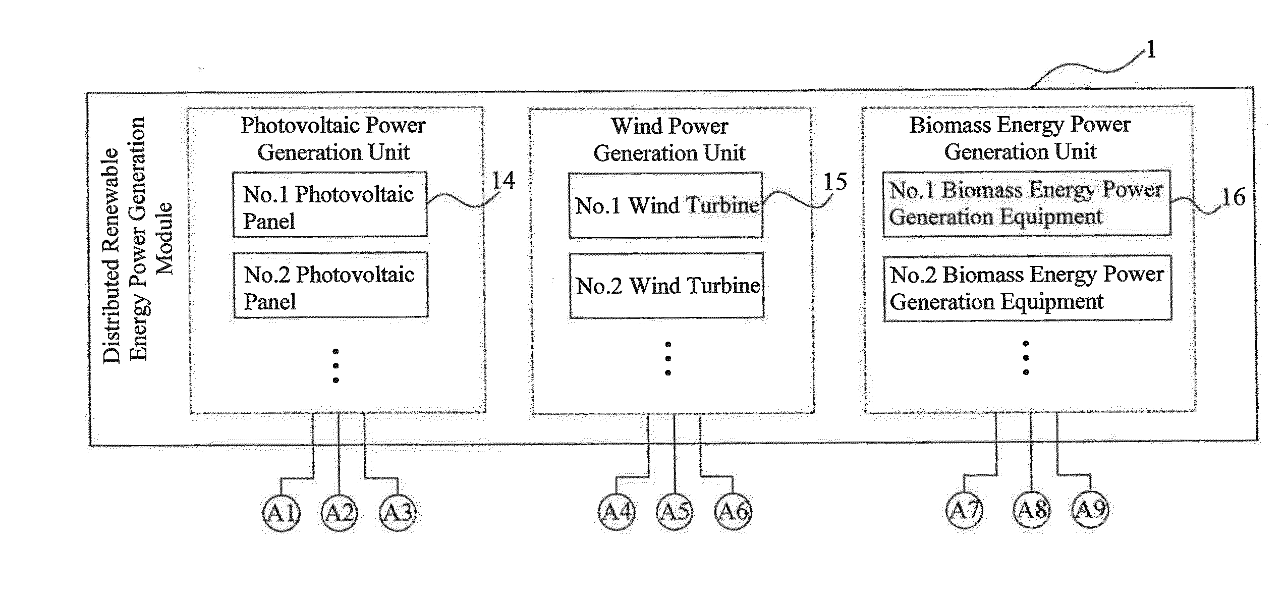
The patent describes an energy resource-grid-load automatic control system for a smart microgrid which uses distributed renewable energy power generation units. The system monitors and predicts the power generation states of all units, adjusts the ratio of electric energy released from each unit to the total required energy, and ensures the stability of the power generation system and the highest rate of energy utilization. Compared to conventional microgrids, the system has higher efficiency and better environmental protection. Additionally, the patent describes an intelligent energy storage module with an intelligent energy storage unit adjuster that solves the problem of nonuniform use of storage batteries and improves energy storage efficiency of the system. The patent also describes an intelligent optimizing power consumption controller that can reasonably predict and adjust the future power consumption of each power generation unit in the system, prevent possible faults and potential hazards, and improve overall efficiency and stability of the microgrid.

Problems solved by technology

However, there are still some drawbacks of the main modes of generation, transmission and distribution of electric energy in response to the flexibility of load variation and the safety of power supply.
In recent years, the energy crisis and the power failure of large power grids occur frequently.
The power crisis and the large-scale power failure reveal that the existing huge power systems have defects.
(1) It is possible that the fault of any point in the large power grids seriously affects the whole power grid, and even results in the large-scale power failure and the power grid collapse.
(2) The large power grids cannot flexibly follow the load variation.
(3) In some remote areas, the power supply is not ideal, because of long distance from power systems, harsh natural conditions, too large investment in power transmission and distribution construction or infeasibility of erection of power transmission and distribution lines.
(4) In recent years, large power grids are often the targets of terrorist attacks and wars, and consequences will be unimaginable once these large power grids are destroyed.
Moreover, the global primary energy suffers from exhaustion increasingly, and the environmental pollution caused by power generation, including acid rain, greenhouse effect and electromagnetic pollution, is becoming more and more obvious.
If a distributed renewable energy microgrid is accessed to a distribution network, the structure of the power grid will be greatly affected, and accordingly the power grid including the microgrid needs to be replanned.
However, conventional problems of power grid planning, such as load optimization, substation optimization and reactive power optimization, and a series of new problems of microgrid access points and access capacity optimization remain to be solved.
It is difficult that the diversified demands of distribution users for the quality of power supply are satisfied as far as possible under the condition of stable operation of the large power grids.
However, the renewable energy power generation and the energy storage equipment in the microgrid cannot be coordinated well, and the intelligent control of loads cannot he achieved in the prior art, thereby greatly hampering the development of the distributed power generation system.

Method used


Image

  • Energy resource-grid-load automatic control system of smart microgrid and control methods thereof
  • Energy resource-grid-load automatic control system of smart microgrid and control methods thereof
  • Energy resource-grid-load automatic control system of smart microgrid and control methods thereof

Examples


Embodiment Construction

[0057]The present invention is further described by figures and the embodiment as follows:

[0058]In the embodiment, an energy resource-grid-load automatic control system of smart microgrid and control methods thereof can be further explained as a system and control methods thereof, which are applicable to the smart microgrid and automatically control power supply, power grids and loads.

[0059]In the embodiment, the type of the wind turbines is SN-1000W. The type of the photovoltaic panels is SN-120W. The type of the micro gas turbines is DTE846. The type of the Digital Signal Processor (DSP) is TMS320F2407A. The inverters are MM440 single-phase-input and three-phase-output inverters of 120W. The type of the storage batteries is 6-GFM-200Ah.

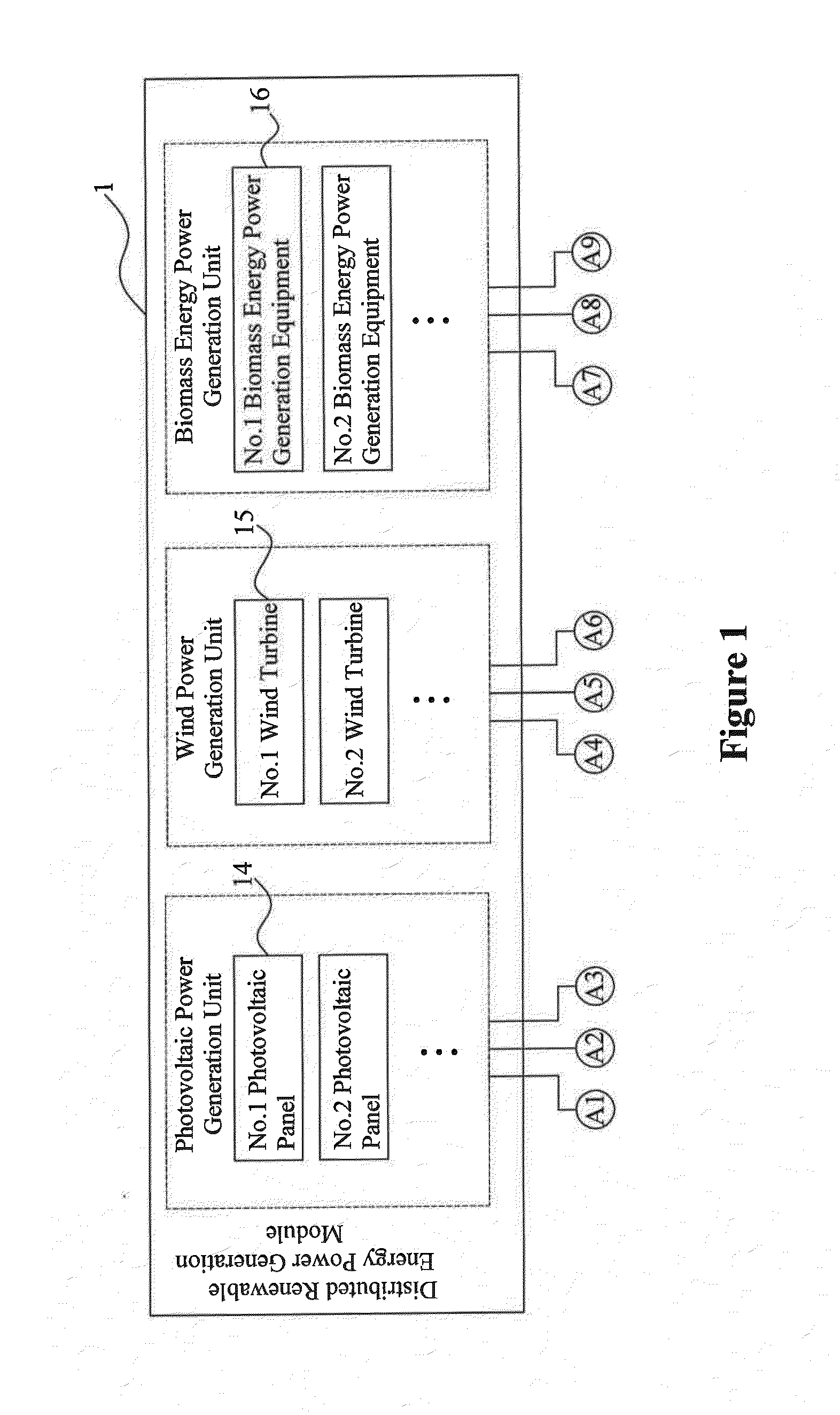
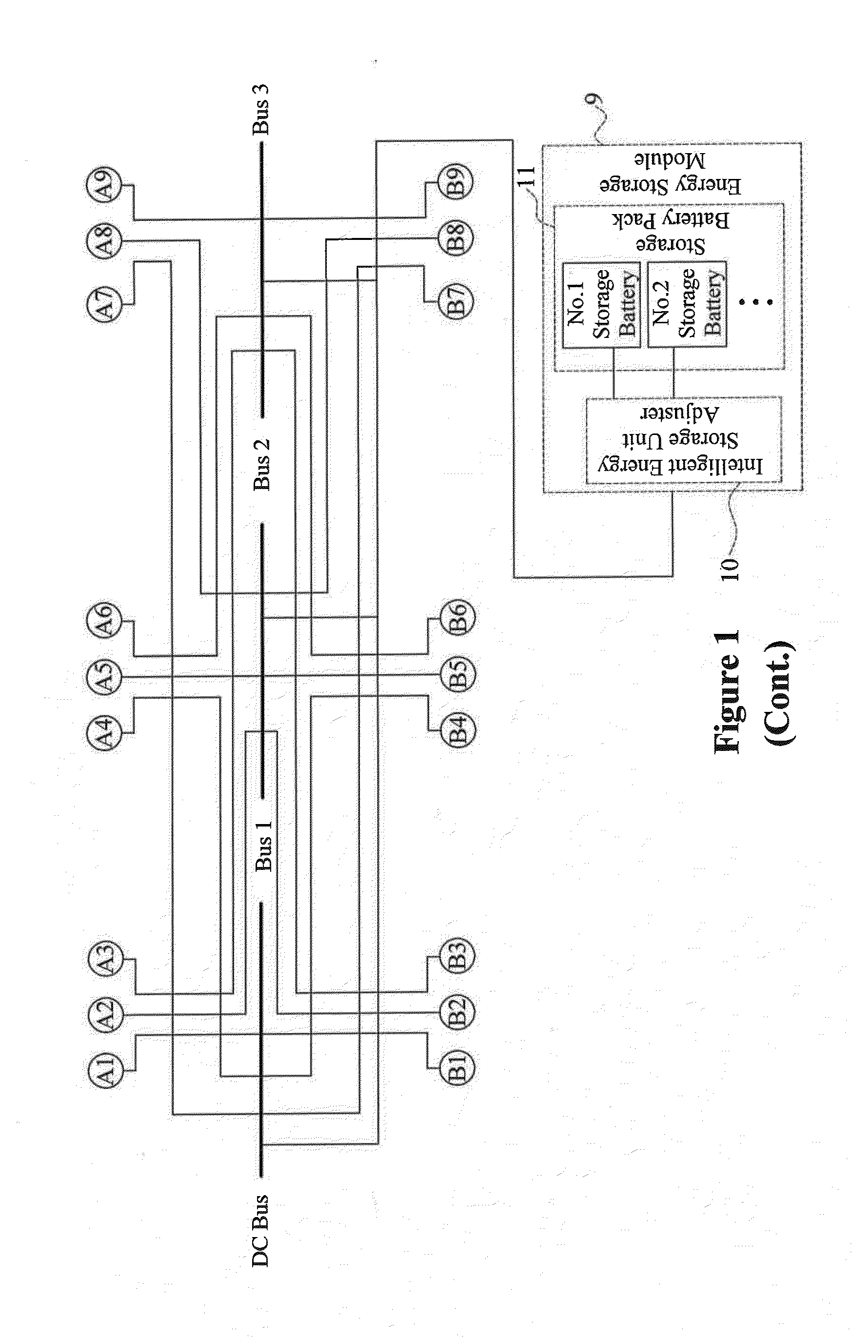
[0060]In the embodiment, as shown in FIG. 1, the energy resource-grid-load automaticcontrol system of smart microgrid comprises the distributed renewable energy power generation module 1, the distributed renewable energy inverter module 2, the distr...


PUM


Abstract

The present invention relates to an energy resource-grid-load automatic control system of smart microgrid and control methods thereof, which belong to the field of microgrid control and electrical technology. The energy resource-grid-load automatic control system comprises a distributed renewable energy power generation module, a distributed renewable energy inverter module, a conventional power generation module, a user load module, a bidirectional grid-connected control module, a distributed renewable energy intelligent optimizing power generation control module, an energy storage module, an intelligent energy storage unit adjuster and a storage battery pack. Compared with the conventional microgrid comprising a distributed renewable energy power generation system, the present invention guarantees the stability and the high energy utilization of the power generation system and effectively solves the problem of non-uniform frequency of use of storage batteries to unify the service life of the storage battery pack.

Description

CROSS-REFERENCE TO RELATED APPLICATION[0001]This application claims the priority of Chinese patent application No. 201310099733.0, filed on Mar. 26, 2013, which is incorporated herewith by reference.BACKGROUND OF THE INVENTION[0002]1. Field of the Invention[0003]The present invention relates to an energy resource-grid-load automatic control system of smart microgrid and control methods thereof, which belong to the field of microgfid control and electrical technology.[0004]2. The Prior Arts[0005]With the economic development and the progress of science and technology, the decentralized and small-scale power systems have been gradually replaced by central stations with large-capacity and high-parameter units and by the modes of extra-high voltage long distance transmission and large grid interconnected and centralized power supply in pursuit of scale benefit in the industrial era. However, there are still some drawbacks of the main modes of generation, transmission and distribution of...

Claims


Application Information

Patent Timeline
Patent Type & Authority Applications(United States)
IPC IPC(8): G05B15/02
CPCG05B15/02Y02E70/30Y02P80/14G06Q50/06H02J3/32H02J7/34H02J9/066H02J3/003H02J2203/20H02J2300/40H02J2310/10H02J2300/10H02J2300/20H02J3/381Y02B10/70H02J2300/24H02J3/007H02J2300/28Y02E10/56
Inventor ZHANG, HUAGUANGSUN, QIUYEYANG, JUNLIU, XINRUIWANG, ZHILIANGTENG, FEIGUO, JINGWANG, ZHANSHANLIU, ZHENWEIWANG, YINGCHUN
Owner NORTHEASTERN UNIV
Learn More