
Method and system for regulating power in the event of at least one aircraft engine failure

a technology of aircraft engine and power regulation, which is applied in the direction of machines/engines, energy-efficient board measures, instruments, etc., can solve the problems of limiting the capacity for acceleration, insufficient power to ensure propulsion as well as the restoration of acceptable,

Active Publication Date: 2014-10-09
SAFRAN HELICOPTER ENGINES
View PDF5 Cites 19 Cited by
  • Summary
  • Abstract
  • Description
  • Claims
  • Application Information

AI Technical Summary

Benefits of technology

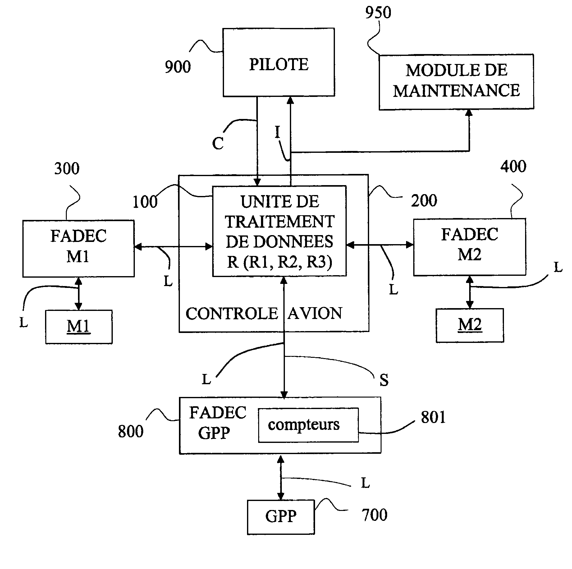
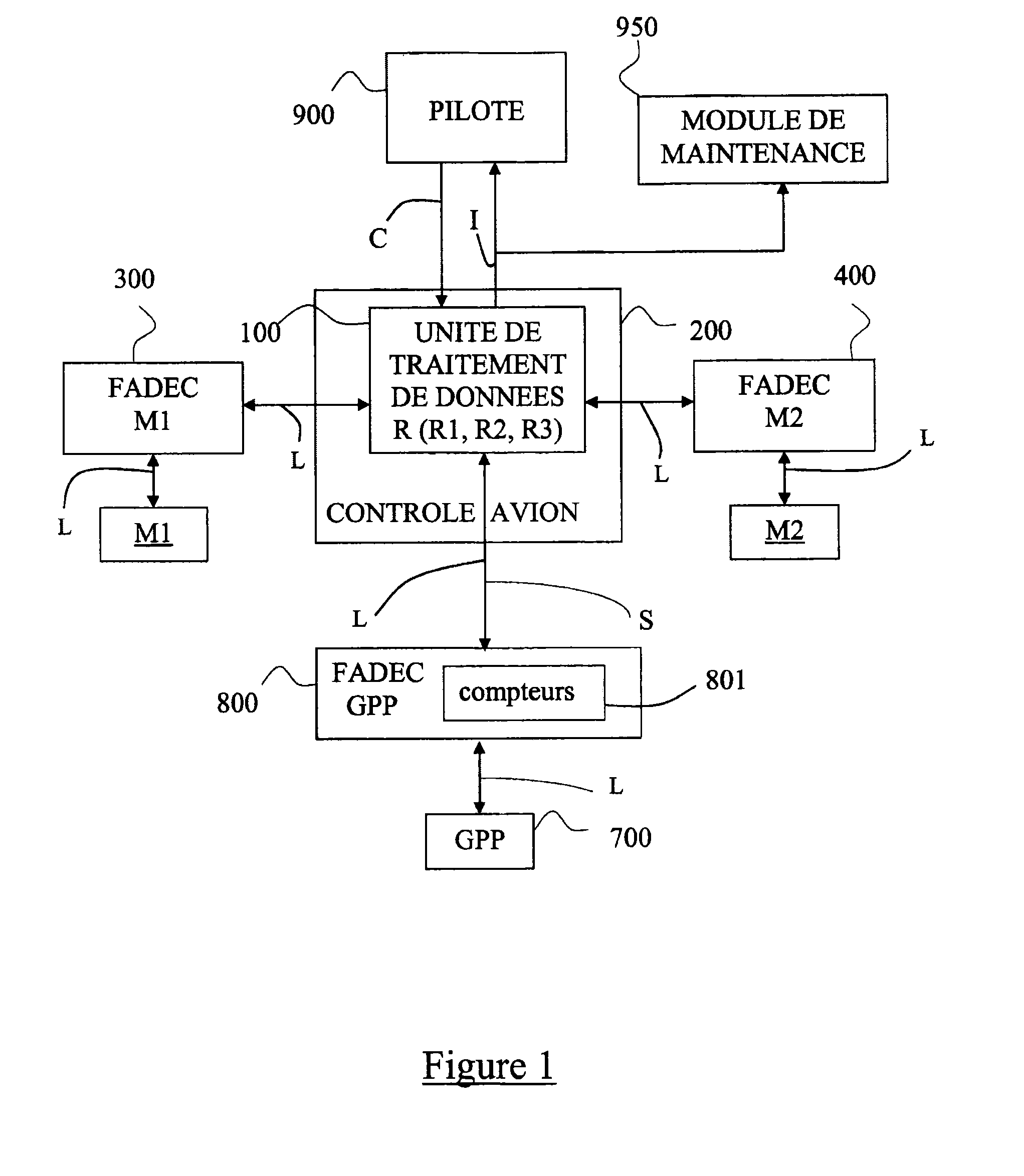
The invention relates to a system for regulating power in an aircraft if one of its engines fails. The system uses different power regimes based on the loss of an engine to provide emergency situations. The system includes an aircraft control, a maintenance module, and a GPP unit. The system uses data from elapsed time counters and information on the state of the engines and GPP unit to manage the demand from the consumers and optimise preventive maintenance. The technical effects of the invention are that it provides additional resources to regain acceptable flight regimes and minimize the impact on the remaining operational engines.

Problems solved by technology

However, although the engines are oversized so as to provide surplus power in particular circumstances, for example in the OEI regime, it seems that this power is insufficient to ensure propulsion as well as restoration of acceptable flight conditions in all phases of flight, and also all the non-propulsive power demands required for the consumers (cabin air conditioning, landing gear etc.).
In particular, the scale of the demands may limit the capacity for acceleration during transitional phases.
However, using an APU in flight means that it has to be restarted, and requires the aircraft to descend below a given altitude, to allow it to generate sufficient pneumatic power.
The activation of the APU thus results in several drawbacks: restarting the APU requires additional work load and monitoring at a time when the pilot has to retain all his concentration; the APU has a restart time of around 90 seconds, which means that it cannot be of immediate assistance; modified flight plan, with a lower ceiling than the maximum permitted if a main engine is lost, to allow the APU to generate sufficient pneumatic power; if the aircraft has to remain above a certain altitude, the APU supplies only electrical power and the surviving engine(s) is / are not completely relieved of power demands.

Method used


Image

  • Method and system for regulating power in the event of at least one aircraft engine failure
  • Method and system for regulating power in the event of at least one aircraft engine failure
  • Method and system for regulating power in the event of at least one aircraft engine failure

Examples


Embodiment Construction

[0012]The aim of the invention is to eliminate these drawbacks. To achieve this, the power contributed is supplied by generation of additional non-propulsive power, operating constantly, and produced by an additional, engine-class main power unit (abbreviated to GPP for “groupe de puissance principal” in French). A power unit is described as engine-class when the architecture and performance of the power generated is suitable for certification as an engine for use in all flight phases, on the same basis as the generation of power supplied by a main aircraft engine. A GPP comprises a gas generator, with dimensions intermediate between a conventional APU and a main aeroplane engine.

[0013]The generation of additional power of the GPP type is calculated so that it can promptly take up all or some of the non-propulsive power requirements of the aircraft. The constant use of a GPP can be adjusted depending on whether the requirements are both pneumatic and electrical, or mainly electrical...


PUM


Abstract

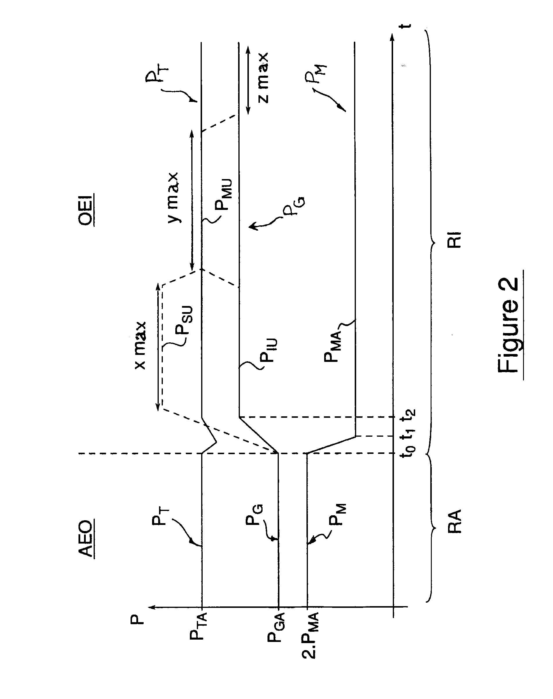
A method to optimize resources needed to continue flight if at least one main engine is lost, by relieving a propulsion system that has remained operative of all or some of non-propulsive energy demands, by additional generation of non-propulsive power, operating continuously. The method uses a GPP unit that operates constantly in flight while taking up some of nominal total non-propulsive power of the aircraft, to supply increased non-propulsive power almost instantaneously, based on at least three respective emergency regimes at a time of engine failure. A control and monitoring function of the GPP calculates elapsed time for each emergency regime, and informs a data processing unit thereof, while emitting an alarm if operating periods allocated to each emergency regime are exceeded, and the emergency function adjusts non-propulsive power demands made by the aircraft between main engines and the unit GPP either automatically or on orders of a pilot.

Description

TECHNICAL FIELD[0001]The invention relates to a method and a system for regulating power in the event of the failure of at least one aircraft engine.[0002]The invention applies to the traction system of aircraft, in other words essentially both the traction system of aeroplanes (jet engines, turbojet engines, turboprop engines) and the traction system of helicopters (turboshaft engine).[0003]Put simply, an aircraft engine conventionally comprises a compressor / combustion chamber / turbine assembly forming a gas generator. After combustion, the hot compressed gases are expanded in the turbine, which drives the compressor mechanically via a high-pressure (abbreviated to HP) shaft, to form the HP body. These gases therefore generate propulsive power and also, in nominal AEO operating conditions (abbreviation of “all engines operating”), non-propulsive, i.e. electrical and / or pneumatic, power.[0004]The energy thus provided during the period corresponding to a level of instantaneous power t...

Claims


Application Information

Patent Timeline
Patent Type & Authority Applications(United States)
IPC IPC(8): B64D31/00
CPCB64D31/00B64D41/00F02C9/00F05D2270/09Y02T50/50B64D31/09B64D31/06
Inventor PRESSE, JEAN-MICHEL
Owner SAFRAN HELICOPTER ENGINES
Learn More