Resonant fiber based aerosol particle sensor and method

a technology of aerosol particles and sensors, applied in the direction of material analysis using microwave means, weighing by absorbing components, and material analysis using sonic/ultrasonic/infrasonic waves. it can solve the problems of nano-sized particle weight determination, inability to use vacuum in combination with ion optics, and inability to manually arrange nano-sized particles on micro strings

Inactive Publication Date: 2014-10-16
DANMARKS TEKNISKE UNIV
View PDF20 Cites 47 Cited by
  • Summary
  • Abstract
  • Description
  • Claims
  • Application Information

AI Technical Summary

Benefits of technology

[0020]Furthermore, the velocity of the flow of aerosol past the one or more elongate members is preferably set sufficiently high to secure that deposition of the particles on the elongate member(s) is caused by inertial impaction. This advantageously means that the velocity of the aerosol produced is higher than 1 m / s. It is noted, that although deposition caused by intertial impaction is the dominant way of deposition at velocities >1 m / s, some deposition may still be caused by diffusion. By dominant is meant that the deposition rate of one collection mechanisms is at least 5 times higher than the deposition rate of the other collection mechanism.
[0021]In the case of electrostatic precipitation of charged nanoparticles on a counter-charged elongate member—that is, the electrostatic elongate member(s) being electrostatic charged to attracts electrostatic charged nanoparticles—the aerosol velocity may be smaller than 1 m / s.

Problems solved by technology

One of the more delicate issues in determining the characteristics of aerosols is determination of the weight of nano-sized particles due to inter alia the inherent small dimensions.
However, such manual arrangement of nano-sized particles on micro strings or utilising vacuum in combination with ion optics appear impractical.
However, the system according to U.S. Pat. No. 5,572,322 is prone to in-accurate measurements of the particle weight as the deflection of the aerosol and thereby also the particles will result in that lighter particles escapes deposition on the surface of the crystal oscillator and only the heavier ones will deposit on the surface of the crystal oscillator.
Thus, the deposition of substance on the sensor according to WO2008 / 020903 is limited to know, specific substances which is attracted to the surface of a recessed sensor and the sensor is not applicable to determine the weight of e.g. unknown airborne substances.
Thus, while different measurement techniques are suggested to measure the weight of nano sized particles, they still suffer from the drawback of measuring in a practical manner the weight of representative, i.e. not only heavier ones, nano-sized particles.

Method used


Image

  • Resonant fiber based aerosol particle sensor and method
  • Resonant fiber based aerosol particle sensor and method
  • Resonant fiber based aerosol particle sensor and method

Examples


Embodiment Construction

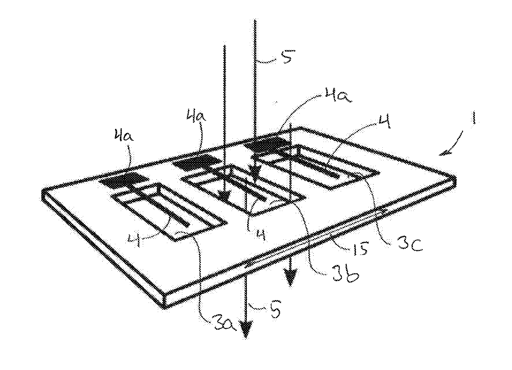
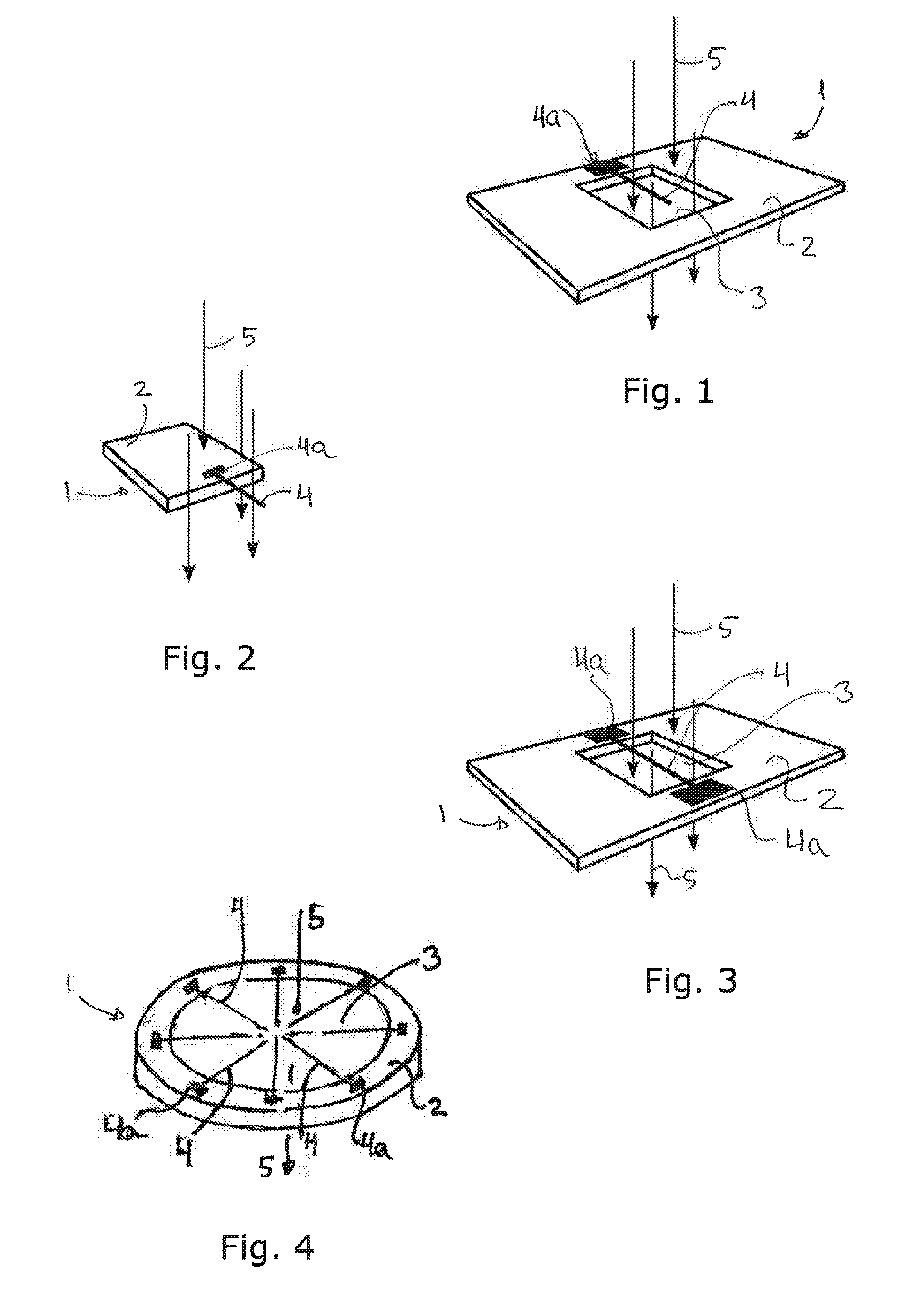
[0058]FIG. 1 shows schematically a sensor element 1 according to a first embodiment of the invention. The sensor element 1 comprises a base member 2 having a square shaped penetration 3 forming a flow passage in the element 1. It is noted that the penetration may have other shapes than square shaped. An elongate member 4 is attached to the base member 2 at one distal 4a and extends from the base member 2 at least partially over the penetration 3. Thus, the elongate member 4 extends in a straight manner out from the base member 2, so as not to extend along and above the surface of the base member 2. Thereby, an incoming flow of e.g. an aerosol is able to flow past the elongate member 4 without flowing towards the base member 2 which could otherwise induce strong curvature in the stream lines—e.g. like an impinging jet flow situation—which results in uneven deposition of particles on the elongate member 4.

[0059]In many of the embodiments of the invention, the base element 2—or in gene...


PUM

PropertyMeasurementUnit
velocityaaaaaaaaaa
velocityaaaaaaaaaa
velocityaaaaaaaaaa

Abstract

The present invention relates to methods and devices for determining the weight of small particles, typically being nano-sized particles by use of resonating fibers in the form of elongate members being driven into resonance by an actuator or e.g. thermal noise/fluctuation. The frequency shift in resonance frequency due to depositing of nano-sized particles is correlated with the mass deposited on the elongate member and the vibration frequency of the elongate member is determined by a detector. The read-out from the detector is transformed into a mass deposited on the elongate member. Particles are deposited by letting a fluid with the particles flow past the elongate member.

Description

FIELD OF THE INVENTION[0001]The present invention relates to methods and devices for determining the weight of small particles, typically being nano-sized particles by use of resonating fibers in the form of elongate members being driven into resonance by an actuator or e.g. thermal noise / fluctuation. The frequency shift in resonance frequency due to depositing of nano-sized particles is correlated with the mass deposited on the elongate member and the vibration frequency of the elongate member is determined by a detector. The read-out from the detector is transformed into a mass deposited on the elongate member. Particles are deposited by letting a fluid with the particles flow past the elongate member.BACKGROUND OF THE INVENTION[0002]During recent years an increasing demand for detecting characteristics of aerosols has arisen. One of the more delicate issues in determining the characteristics of aerosols is determination of the weight of nano-sized particles due to inter alia the ...

Claims


Application Information

Patent Timeline
Patent Type & Authority Applications(United States)
IPC IPC(8): G01N33/00G01N15/02
CPCG01N29/022G01N2291/0256G01N2291/0427G01N33/0004G01N5/02G01N9/002G01N15/0255G01N29/036
Inventor SCHMID, SILVANBOISEN, ANJA
Owner DANMARKS TEKNISKE UNIV
Why Eureka
Try Eureka