System and method for gas purge control

a technology of gas purge control and system, which is applied in the direction of electrical control, mechanical equipment, machines/engines, etc., can solve the problems of reducing the amount of vacuum may not be enough to drive the gas purging from the above systems, and the stale air system in the crankcase ventilation system, etc., to reduce the amount of purge flow, reduce the amount of vacuum in the intake manifold, and reduce the amount of flow

Active Publication Date: 2014-10-30
FORD GLOBAL TECH LLC
View PDF13 Cites 66 Cited by
  • Summary
  • Abstract
  • Description
  • Claims
  • Application Information

AI Technical Summary

Benefits of technology

[0003]In such approaches, the flow rate of the gas streams delivered to the engine may be a function of intake manifold vacuum so that the amount of vacuum available to the aforementioned systems may change in response to engine operating conditions. For example, during high intake flow conditions in the engine, the amount of vacuum in the intake manifold may decrease so that a reduced amount of flow occurs in one or more of a crankcase ventilation system, a fuel vapor purge system, and an EGR system. In particular, as an intake throttle is opened to a greater extent the manifold vacuum may diminish and thus may result in a stale air system in a crankcase ventilation system. As another example, the amount of purge flow may decrease during conditions where the engine can consume a higher amount of fuel vapor, e.g., during high engine intake flow conditions. In particular, at a constant engine speed, as the air flow rate increases, the vacuum pulling the purge vapor into the engine decreases during conditions when a higher purge flow rate may be desired.
[0004]Further, in some approaches, in order to decrease emissions and increase output engines may be operated with an intake volume downstream of a throttle approaching barometric pressure. In engine applications that operate with low vacuum air induction, or near atmospheric pressure (as measured post throttle body in the engine's intake manifold), the small amount of vacuum may not be enough to drive gas purging from the aforementioned systems (e.g., EGR systems, evaporative emissions systems, and / or crankcase ventilation systems). More particularly, in hybrid electric vehicle (HEV) applications, the engine run time may be shorter than the amount of time it takes to purge gas from the aforementioned systems with a low vacuum, such as from a fuel vapor canister.
[0006]In this way, gas delivery rates from crankcase ventilation systems, emission control systems, and EGR systems may be delivered in proportion to engine air flow rate during different engine operating conditions. For example, an amount of crankcase ventilation flow and an amount of fuel vapor purge flow may increase during high engine intake flow conditions when an increase in flow in such systems is desired. Such an approach may further provide a consistent uni-directional flow through a crankcase ventilation system this enabling positive crankcase ventilation under all conditions.

Problems solved by technology

In particular, as an intake throttle is opened to a greater extent the manifold vacuum may diminish and thus may result in a stale air system in a crankcase ventilation system.
As another example, the amount of purge flow may decrease during conditions where the engine can consume a higher amount of fuel vapor, e.g., during high engine intake flow conditions.
In engine applications that operate with low vacuum air induction, or near atmospheric pressure (as measured post throttle body in the engine's intake manifold), the small amount of vacuum may not be enough to drive gas purging from the aforementioned systems (e.g., EGR systems, evaporative emissions systems, and / or crankcase ventilation systems).

Method used


Image

  • System and method for gas purge control
  • System and method for gas purge control
  • System and method for gas purge control

Examples


Embodiment Construction

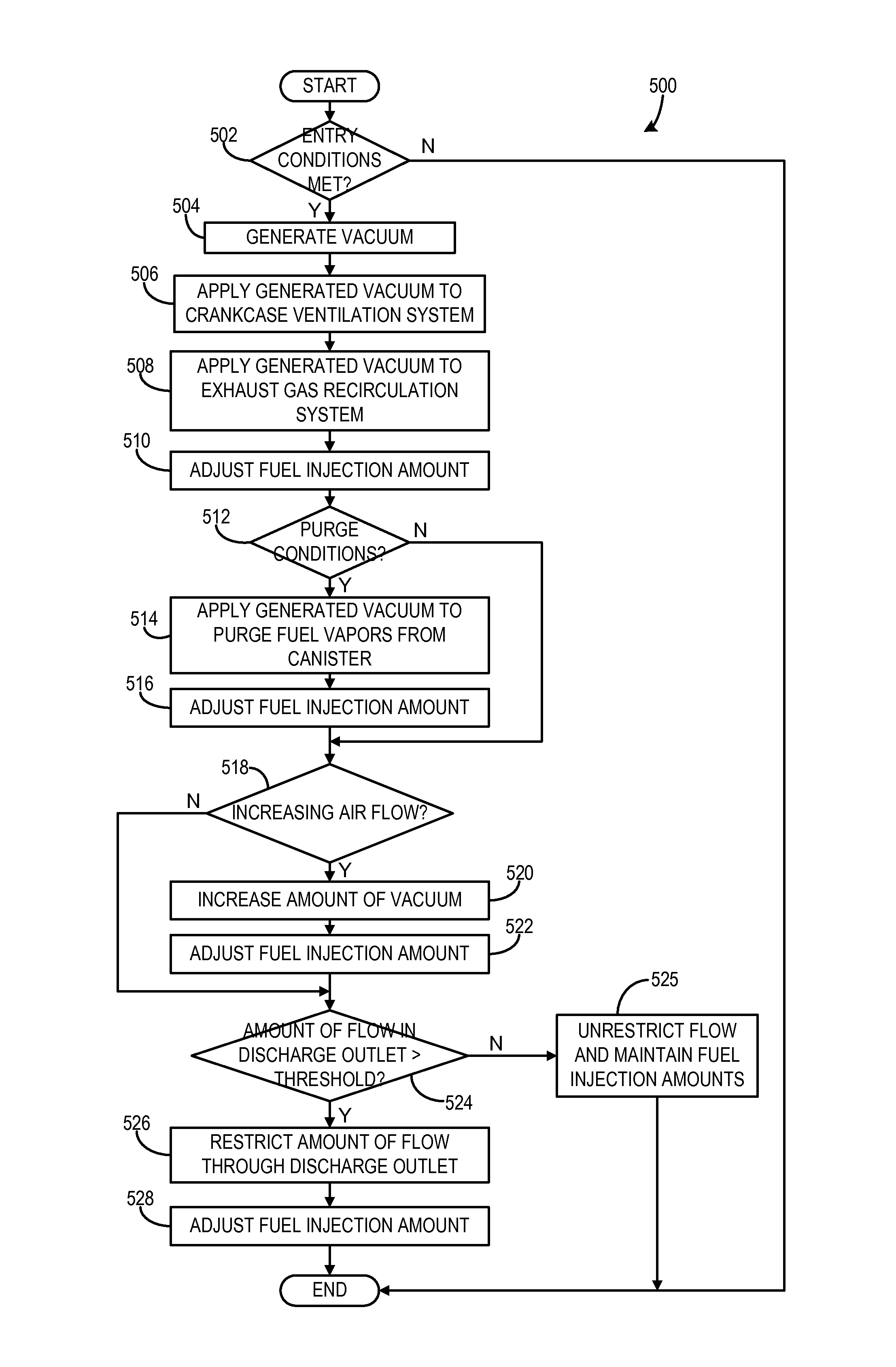
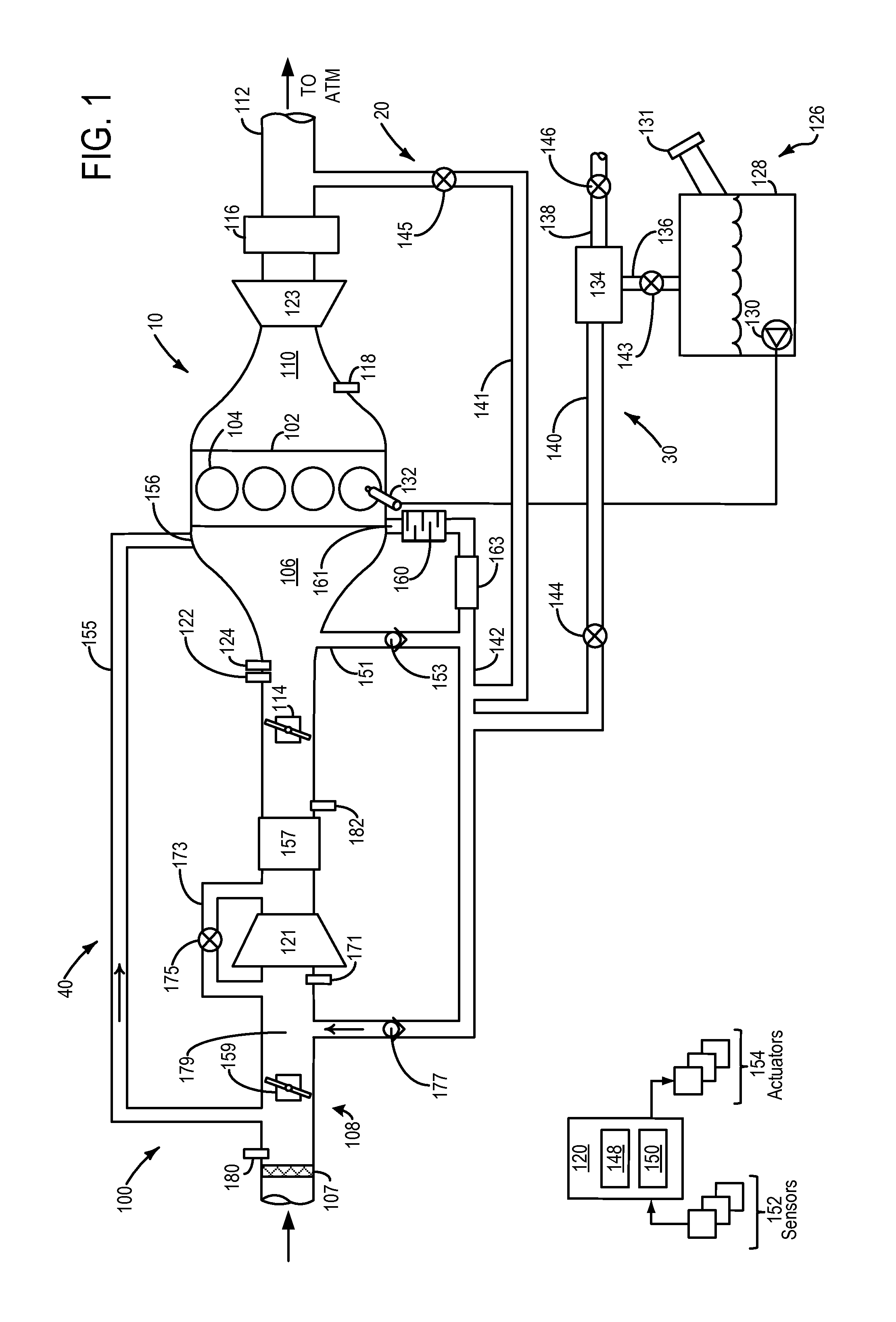
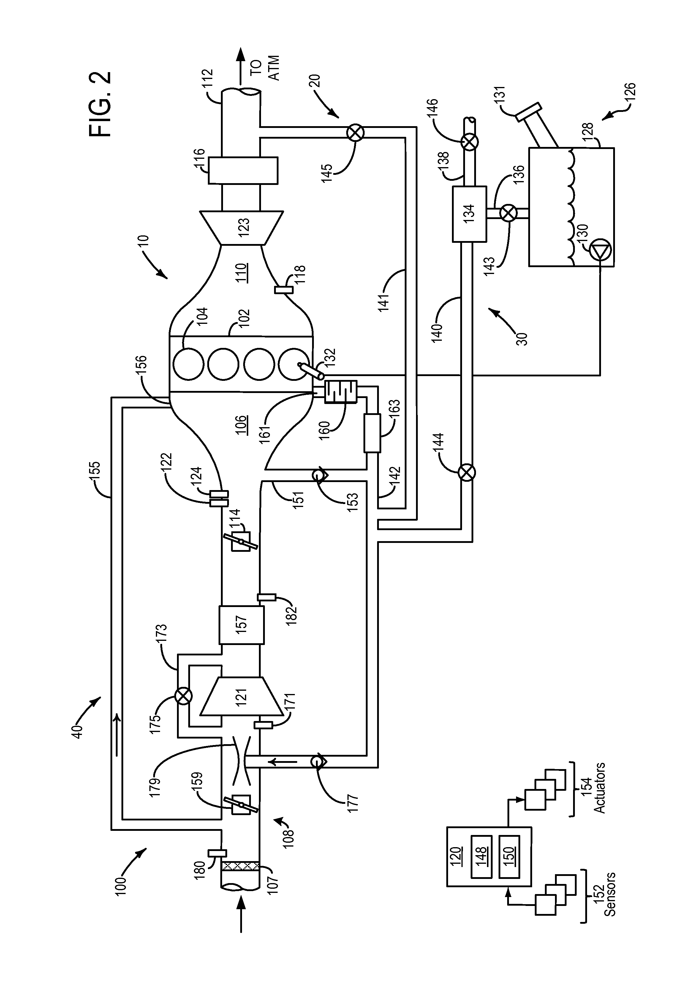
[0010]The present description relates to systems and methods for providing vacuum to one or more of a crankcase ventilation system, an emission control system, and an exhaust gas recirculation (EGR) system included in an engine system, e.g., the engine systems shown in FIGS. 1-4. As shown in FIGS. 1-4, a vacuum source, e.g., an ejector or venturi, may be included in an intake of an engine downstream of a pre-compressor throttle and upstream of an intake throttle and may be used to provide vacuum proportional to a flow rate of engine intake air. As shown in FIG. 5, vacuum generated by the vacuum source in the engine intake may be used to drive consistent flow through a crankcase ventilation system, an emission control system, and an exhaust gas recirculation (EGR) system included in an engine system.

[0011]FIG. 1 schematically shows an example of an engine system 100 according to an embodiment of the present disclosure. Engine system 100 may be included in a vehicle system in order to...


PUM


Abstract

Systems and methods for providing vacuum to one or more of a crankcase ventilation system, an emission control system, and an exhaust gas recirculation (EGR) system included in a turbocharged engine system are provided. In one example, approach, a method comprises drawing vacuum from a vacuum source located in an intake of the engine downstream of a pre-compressor throttle and upstream of an intake throttle, and applying the drawn vacuum to a discharge outlet of a uni-directional crankcase ventilation system, where an inlet of the crankcase ventilation system is coupled to the intake of the engine upstream of the pre-compressor throttle.

Description

BACKGROUND AND SUMMARY[0001]Engines may direct a variety of gas streams to an intake system such as an evaporative emissions system, exhaust gas recirculation (EGR) system, and / or crankcase ventilation system. A vacuum generated in the intake system may be used to drive gas circulation through the aforementioned systems. Valves may be employed on the aforementioned systems to control the amount of gas entering the intake system.[0002]In some approaches, vacuum used to drive gas circulation through the aforementioned systems may be based on engine intake manifold vacuum. For example, a crankcase ventilation system may pull a gas flow rate from the crankcase to positively ventilate the crankcase by relying on intake manifold vacuum. As another example, vacuum generated in the intake manifold may be used to purge fuel vapor stored in a fuel vapor canister in an evaporative emissions system by actuating a purge flow control valve.[0003]In such approaches, the flow rate of the gas stream...

Claims


Application Information

Patent Timeline
Patent Type & Authority Applications(United States)
IPC IPC(8): F01M13/02F02M25/08F02M25/07
CPCF01M13/022F02M25/08F02M25/0712F01M2013/027F02D41/0007F02D41/003F02D41/0042F02D41/005F02D2250/41F02M25/089F02M26/06F02M26/07F02M26/10F02M26/19F02M26/36F02B37/162Y02T10/12Y02T10/40
Inventor PURSIFULL, ROSS DYKSTRA
Owner FORD GLOBAL TECH LLC
Why Eureka
Try Eureka