

Method for fabricating a conductive yarn and conductive yarn fabricated by the method
a technology of conductive yarn and conductive yarn, which is applied in the direction of conductors, applications, non-insulating conductors, etc., can solve the problems of power consumption and time consumption of vapor deposition and plasma chemical deposition, high cost of equipment for plasma chemical deposition, etc., and achieve good conductivity and reduce process period and production cost
- Summary
- Abstract
- Description
- Claims
- Application Information
AI Technical Summary
Benefits of technology
Problems solved by technology
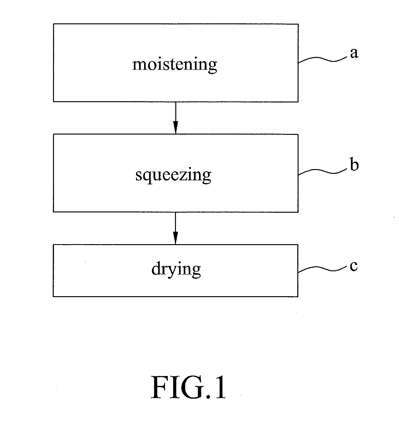
Method used
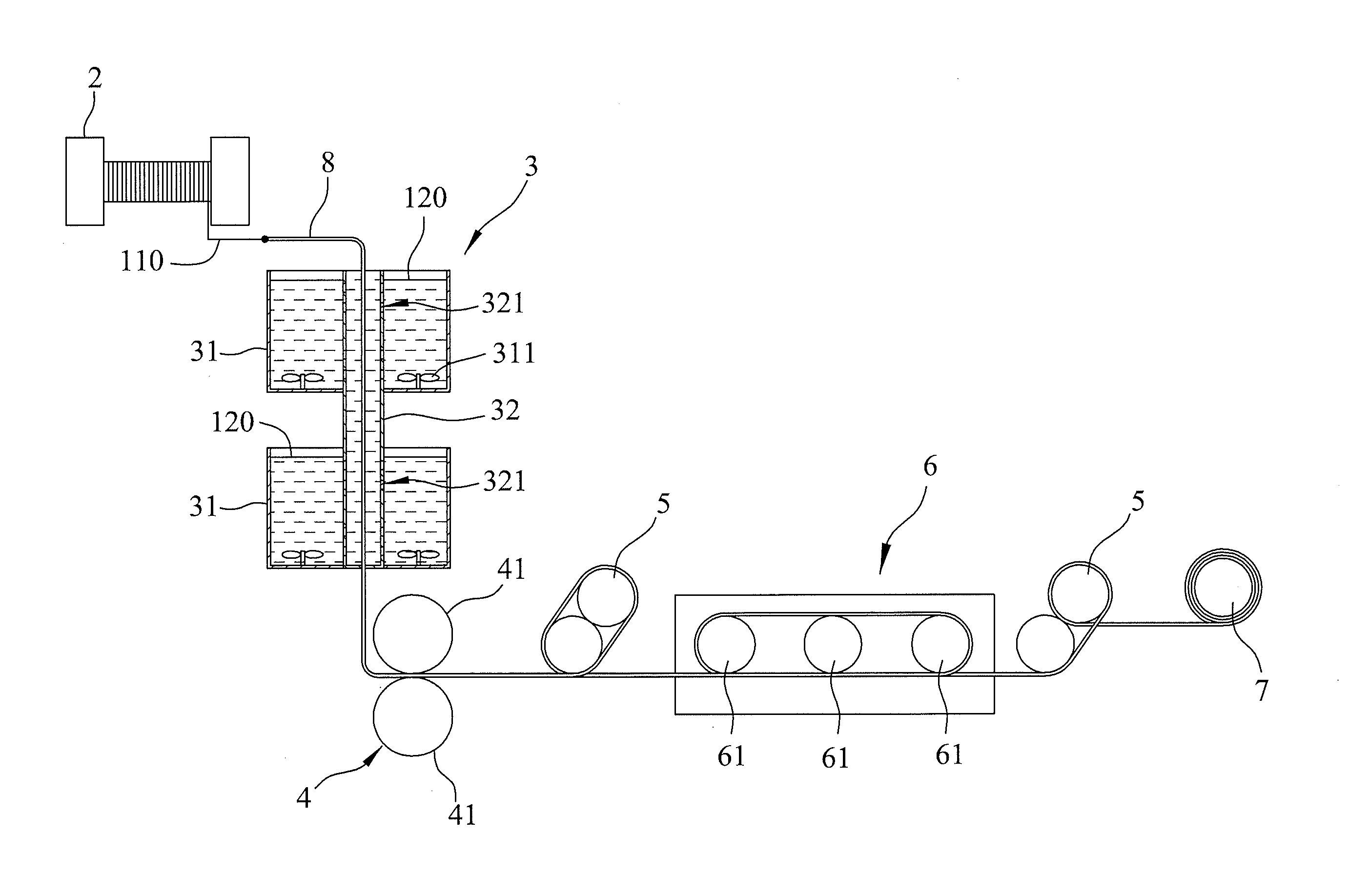
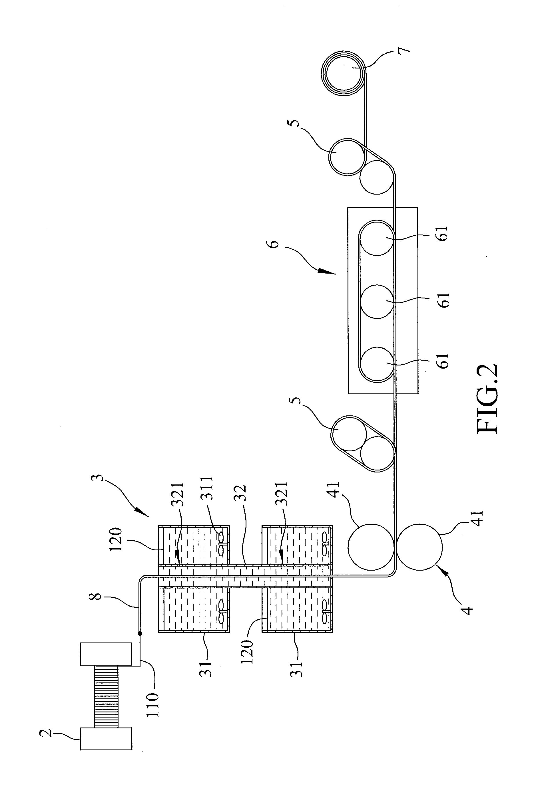
Image

Examples
example 1
[0038]The conductive slurry used in this example is composed of an aqueous resin (a polyurethane resin) in an amount of 44.5 wt %, a thickening agent in an amount of 0.5 wt %, a defoaming agent in an amount of 0.02 wt %, a conductive nano wire made of silver in an amount of 5 wt %, and a solvent (water) in a balance amount based on 100 wt % of the conductive slurry. The aforesaid preferred embodiment of the method for fabricating a conductive yarn according to this invention was performed to obtain a conductive yarn. The conductive nano wires having different aspect ratios were used in
examples 1-1 to 1-6
[0039]The surface resistance of each of the conductive yarns obtained in Examples 1-1 to 1-6 was measured at 10 cm and 100 cm using a multi-meter. The conductivity of each of the conductive yarns obtained in Examples 1-1 to 1-6 was determined by the luminescence of an LED light source connected to the conductive yarns. The result is shown in Table 1.
TABLE 1Examples1-11-21-31-41-5Aspect ratio 1 10 200 225 250 ConductivityXX◯◯◯Surface 10 cm 13 13 222Resistance 100 cm14 14 333(Ω / sqr)
[0040]As shown in Table 1, the aspect ratio of the conductive nano wire is preferably larger than 200. When the aspect ratio of the conductive nano wire is too small (that is, the conductive nano wire is sphere-like), the conductive nano wire may not be absorbed effectively and sufficiently on the preformed yarn using a conductive slurry having a low amount of the conductive nano wire.
[0041]FIG. 3 shows test result of the surface resistances of the conductive yarns at 100 cm. It can be found fr...
example 2
[0042]The conductive slurry used in this example is composed of an aqueous resin (a polyurethane resin) in an amount of 44.5 wt %, a thickening agent in an amount of 0.5 wt %, a defoaming agent in an amount of 0.02 wt %, a conductive nano wire made of silver in an amount ranging from 0.1 wt % to 10 wt %, and a solvent (water) in a balance amount based on 100 wt % of the conductive slurry. The aspect ratio of the conductive nano wire is 200. The aforesaid preferred embodiment of the method for fabricating a conductive yarn according to this invention was performed to obtain a conductive yarn. The amounts of the conductive nano wires in the conductive slurries used in Examples 2-1 to 2-6 are 0.1 wt %, 0.5 wt %, 1 wt %, 3 wt %, 5 wt %, and 10 wt %, respectively. The result is shown in Table 2.
TABLE 2Examples2-12-22-32-42-52-6Amounts of0.10.5 1 3 5 10 conductivenano wire (wt %)ConductivityXΔ◯◯◯◯Surface107-108105-1064433resistance at100 cm(Ω)
[0043]As shown in Table 2, when the ...
PUM
| Property | Measurement | Unit |
|---|---|---|
| aspect ratio | aaaaa | aaaaa |
| temperature | aaaaa | aaaaa |
| aspect ratio | aaaaa | aaaaa |
Abstract
Description
Claims
Application Information