Compound structured light projection system for 3-D surface profiling

a structured light and projection system technology, applied in the direction of instruments, measuring devices, electrical appliances, etc., can solve the problems of incoherent illumination, uniformity, intense illumination of slides, etc., and achieve the effect of high power and high efficiency

Inactive Publication Date: 2014-10-30
JOHNSON PHILIP MARTIN
View PDF2 Cites 87 Cited by
  • Summary
  • Abstract
  • Description
  • Claims
  • Application Information

AI Technical Summary

Benefits of technology

[0020]The bars in each slide on the spinning code disk are all tangentially oriented; that is, all have their long edges perpendicular to a radius of the code disk at their centers. As a result, translational motion of the projected patterns on the object being measured is negligible for a laser pulse duration of a few microseconds, making it possible to use commercially available “quasi-CW” mode high power and high efficiency laser diode arrays.
[0021]Each periodic bar pattern on the code disk has a unique combination of spatial periods and phase shifts, defined by the new extended complementary Gray code sequence of this invention. The extended Gray code sequence makes use of the fact that all of the projected bar images will be detected and measured by digital cameras, each containing a focal plane array of square pixels spaced at a consistent pixel pitch. Each square camera pixel spatially integrates the energy reflected from a small part of the object being measured, that small part being defined by a back-projected image of the pixel itself. The result is that measured pixel signal changes as a linear functio...

Problems solved by technology

The result is uniform, incoherent,...

Method used


Image

  • Compound structured light projection system for 3-D surface profiling
  • Compound structured light projection system for 3-D surface profiling
  • Compound structured light projection system for 3-D surface profiling

Examples


Embodiment Construction

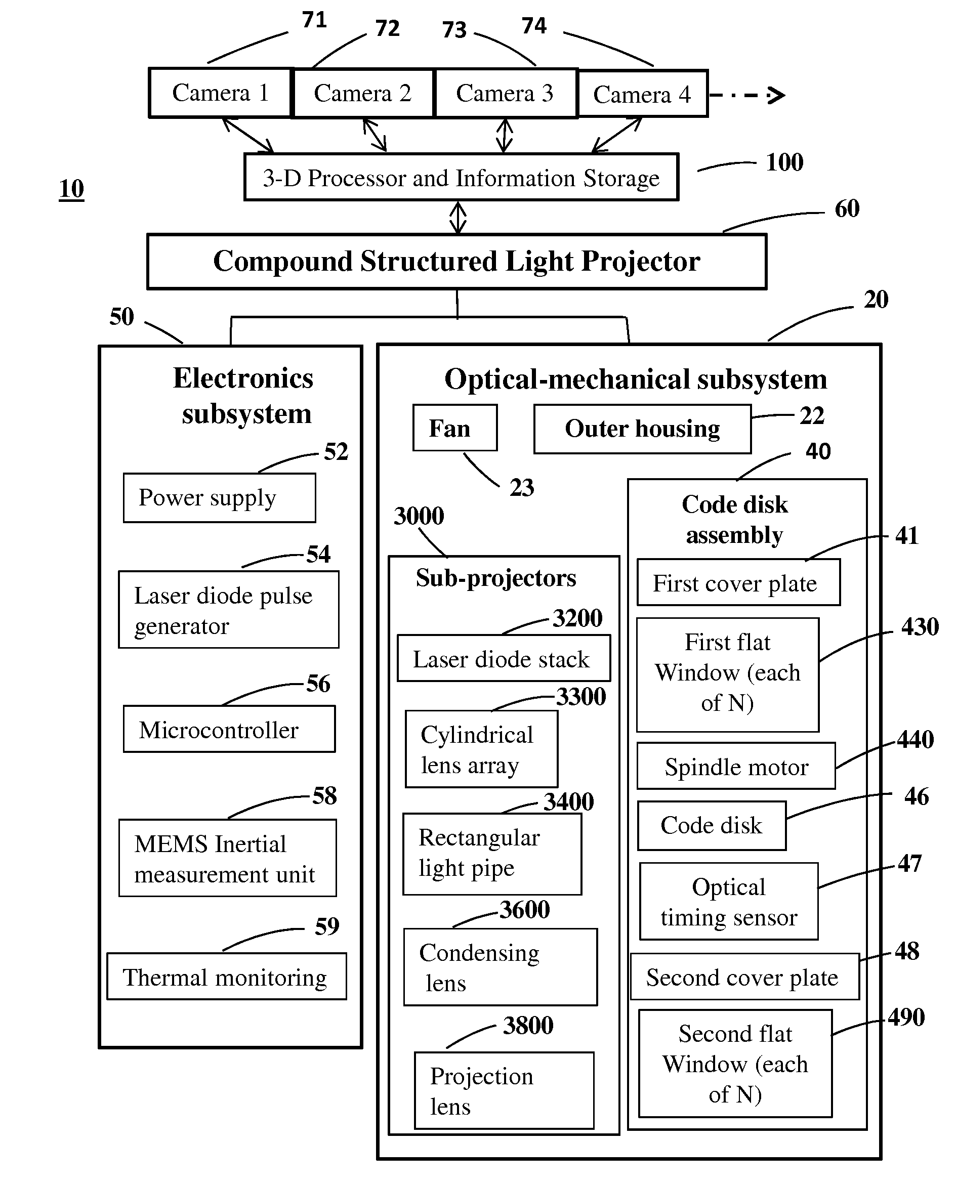
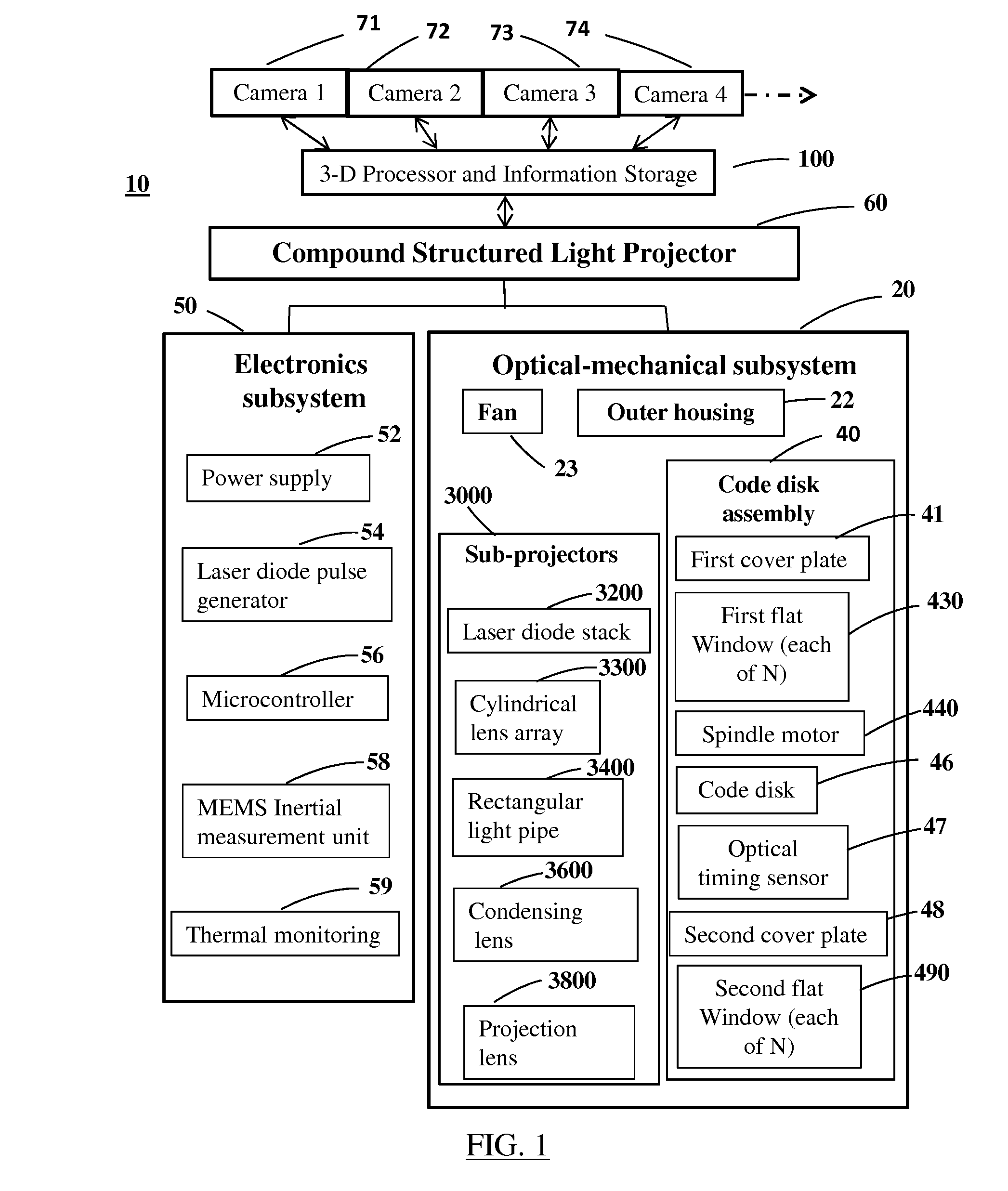
[0043]Referring now to FIG. 1, a system embodying the principles of the present invention is illustrated in block diagram form and designated as 10. The entire system 10 includes a compound structured light projector 60, a plurality of high speed digital cameras 71,72,73,74, etc. and 3-D digital processor and information storage unit 100. The compound structured light projector 60 comprises two major sub-systems: electronics subsystem 50 and optical-mechanical subsystem 20.

[0044]In electronics subsystem 50, power supply 52 converts available input power to various direct current (DC) voltages. Laser diode pulse generator 54 creates pulses at a rate of 12,000 Hz to serve four laser diode stacks in sequence, each being pulsed at 3,000 Hz with approximately 130 amperes of current at 16 volts for a duration of 4 μs. Microcontroller 56 is a small electronic processor that controls the operation of the compound structured light projector 60, including motor speed control and communication...


PUM


Abstract

A method and apparatus is provided for high speed, non-contact method of measuring the 3-D coordinates of a dense grid of points on a surface, including high accuracy interpolation between grid points. A plurality of pulsed laser sub-projectors sequentially illuminates a plurality of discrete Gray code bar pattern transparencies carried on a spinning circular code disk to project high frame rate structured light. The structured light is reflected by the surface and recorded at high signal-to-noise ratio by a plurality of high frame rate digital cameras, then decoded and interpolated by electronic signal processing. A numerical formula is derived for numbers of equally spaced discrete code patterns on the code disk that allow each camera to receive pulses from all sub-projectors and all patterns at a constant frame rate. Methods to derive an extended complementary Gray code pattern sequence and to normalize measured signal amplitudes are presented.

Description

CROSS-REFERENCE TO RELATED APPLICATIONS[0001]This application claims the benefit of Provisional Patent Application Ser. No. 61 / 641,083 filed May 1, 2012, the entire contents of which are hereby incorporated by reference.STATEMENT OF GOVERNMENT INTEREST[0002]This invention was made without United States Government assistance.BACKGROUND OF THE INVENTION[0003]In many manufacturing processes there is a need for automated non-contact 3-D surface profile measuring instruments with improved accuracy and speed. Typical uses of these instruments are for quality control inspection of, for example, stamped metal parts, welds, automobile door closures, bored hole position and dimensional accuracy, and automobile wheel alignment. Such instruments may be stationary and take measurements of stationary or moving objects, or may be mounted on robotic arms to rapidly scan stationary or moving objects from different angles. Robotic arms with many degrees of freedom are now common in automated factorie...

Claims


Application Information

Patent Timeline
IPC IPC(8): H04N13/02
CPCH04N13/0242G01B11/2513G01B11/2536
Inventor JOHNSON, PHILIP MARTIN
Owner JOHNSON PHILIP MARTIN
Why Eureka
Try Eureka