
Bi-polar protected electrodes and multi-cell stacks

a bipolar protection and electrode technology, applied in the water field, can solve the problems of lithium metal in direct contact with seawater, high toxicity of thionyl chloride cells, and inability to meet the requirements of lithium metal, so as to reduce the rate of cell activation, improve conductivity, and reduce the rate of ion exchange

Inactive Publication Date: 2014-11-13
POLYPLUS BATTERY CO INC
View PDF6 Cites 12 Cited by
  • Summary
  • Abstract
  • Description
  • Claims
  • Application Information

AI Technical Summary

Benefits of technology

The patent text describes a new type of battery cell that uses protected electrodes and seawater as its electrolyte. This results in a very lightweight battery cell that can be used underwater. The cell also includes a solid salt that helps improve conductivity and startup performance. Overall, this patent presents a technical solution for creating efficient and reliable batteries that can operate in extreme environments.

Problems solved by technology

Global issues are increasing the need for and expanding the role of underwater devices to monitor, survey, and explore oceans, harbors and coastal water systems.
Moreover, thionyl chloride cells are highly toxic and removal of that battery after underwater deployment presents a serious safety hazard, especially after it has been discharged at high rate.
However, lithium metal in direct contact with seawater is not feasible due to the corrosion reaction of lithium and seawater.

Method used


Image

  • Bi-polar protected electrodes and multi-cell stacks
  • Bi-polar protected electrodes and multi-cell stacks
  • Bi-polar protected electrodes and multi-cell stacks

Examples


embodiment 130

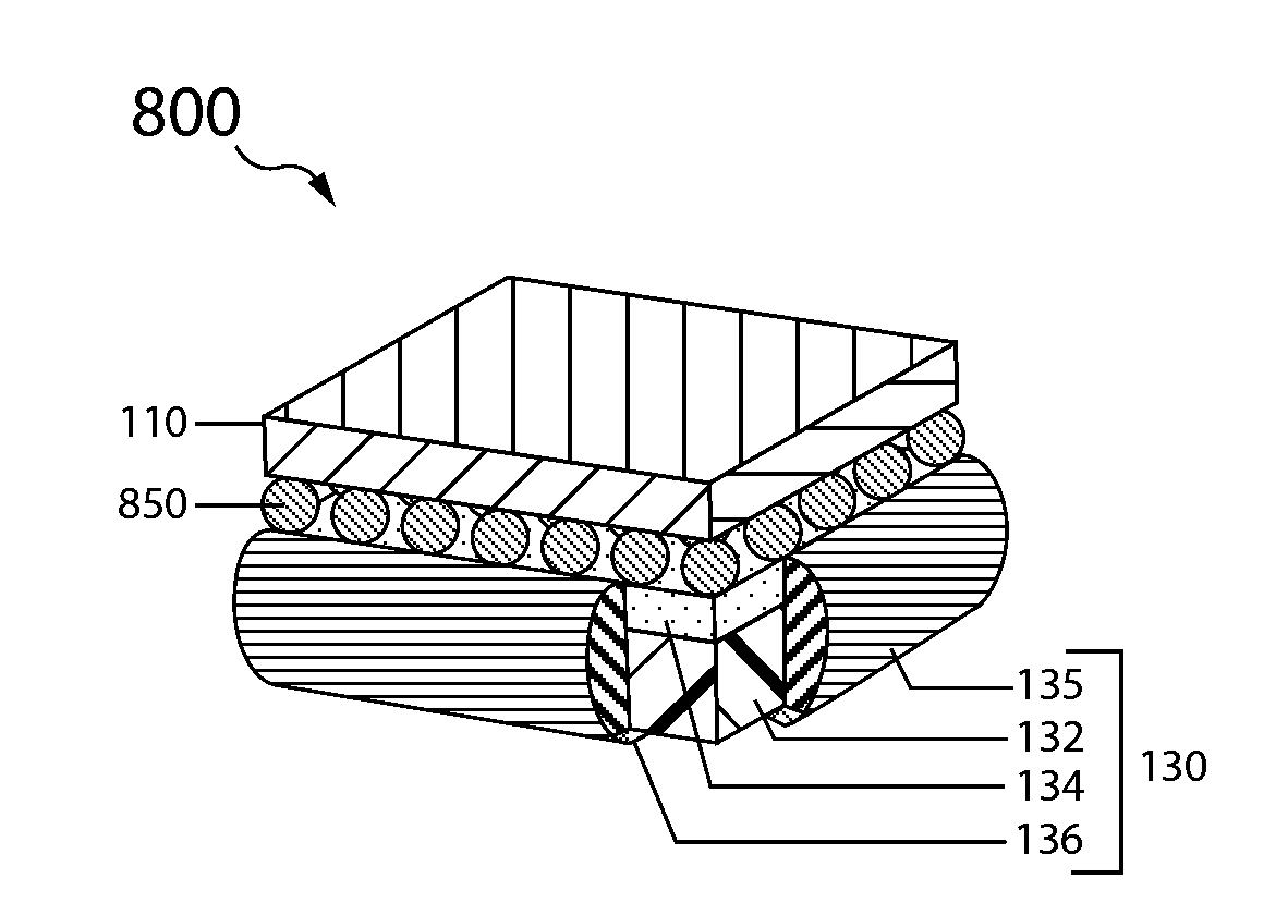
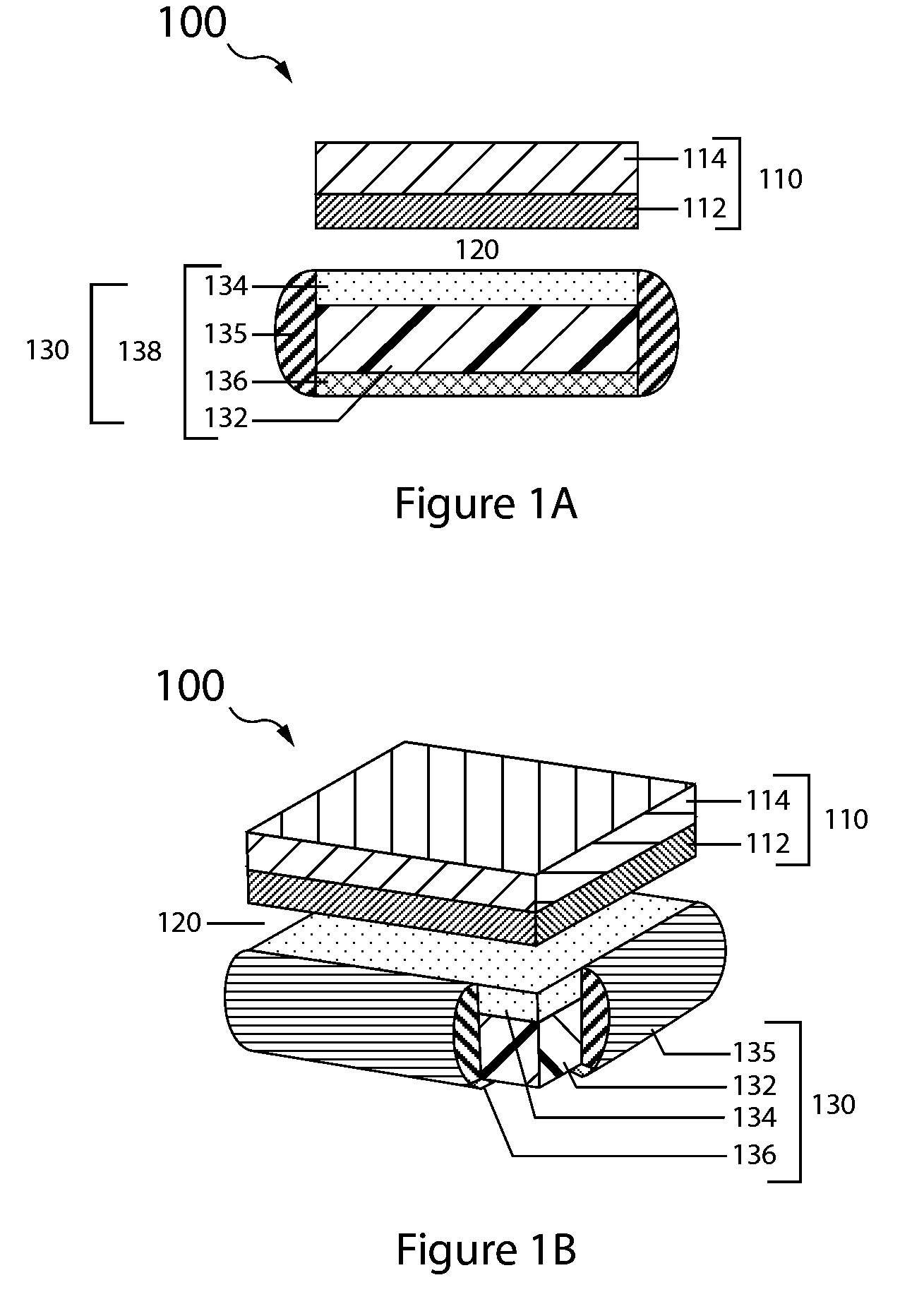
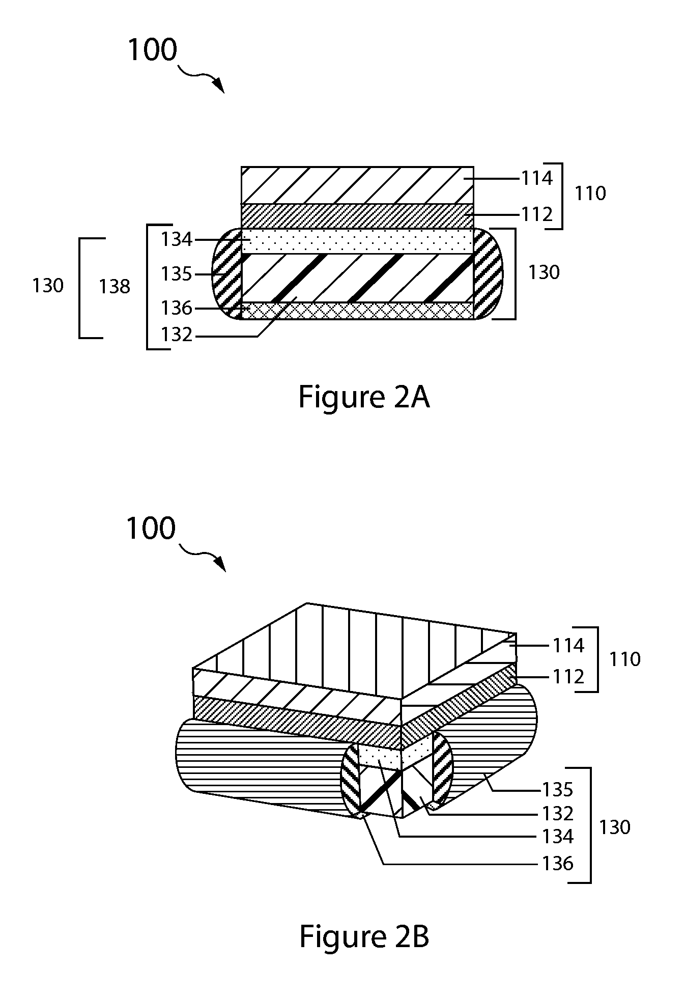
[0079]The anode layer has two opposing surfaces, a first active surface and a second surface. In the double-sided anode embodiment 330 the second surface is active and in the single sided embodiment 130 it is inactive.

[0080]The anode layer 132 is sandwiched between the protective membrane architecture 134 and the anode backplane 136, with the first active surface of the anode layer (e.g., lithium metal foil) opposing, typically in direct contact, the interior surface of the protective membrane architecture, and the anode layer second surface opposing the interior backplane surface.

[0081]A seal structure 135 interfacing with the protective membrane architecture and anode backplane seals the anode layer in an anode compartment, and thus forms the anode enclosure 138.

[0082]With reference to FIG. 3B, the protected anode 330 is double sided and the anode backplane 134 is a second protective membrane architecture arranged in like manner to that of the first protective membrane and therefo...

fourth embodiment

[0098]The composite should have an inherently high ionic conductivity. In general, the ionic conductivity of the composite is at least 10−7 S / cm, generally at least about 10−6 to 10−5 S / cm, and may be as high as 10−4 to 10−3 S / cm or higher. The thickness of the first precursor material layer should be enough to prevent contact between the second material layer and adjacent materials or layers, in particular, the active metal of the anode. For example, the first material layer for the solid state membranes can have a thickness of about 0.1 to 5 microns; 0.2 to 1 micron; or about 0.25 micron. Suitable thickness for the anolyte interlayer of the fourth embodiment range from 5 microns to 50 microns, for example a typical thickness of Celgard is 25 microns.

[0099]The thickness of the second material layer is preferably about 0.1 to 1000 microns, or, where the ionic conductivity of the second material layer is about 10−7 S / cm, about 0.25 to 1 micron, or, where the ionic conductivity of the...


PUM

PropertyMeasurementUnit
gap thicknessaaaaaaaaaa

Abstract

Water activated alkali metal battery cells, protected anode bi-polar electrodes and multi-cell stacks are configurable to achieve very high energy density. The cells, bi-polar electrode and multi-cell stacks include a protected anode and a cathode having a solid phase electro-active component material that is reduced during cell discharge.

Description

CROSS-REFERENCE TO RELATED APPLICATIONS[0001]This application is a divisional of U.S. patent application Ser. No. 12 / 973,779 filed Dec. 20, 2010, titled HIGH RATE SEAWATER ACTIVATED LITHIUM BATTERY CELLS BI-POLAR PROTECTED ELECTRODES AND MULTI-CELL STACKS, which claims priority to U.S. Provisional Patent Application No. 61 / 329,829 filed Apr. 30, 2010, titled HIGH RATE LI / SEAWATER ACTIVATED BATTERY; and U.S. Provisional Patent Application No. 61 / 373,732 filed Aug. 13, 2010, titled HIGH RATE LI / SEAWATER ACTIVATED BATTERY; and U.S. Provisional Patent Application No. 61 / 378,317 filed Aug. 30, 2010, titled HIGH RATE LITHIUM SEAWATER ACTIVATED BATTERY. Each of these prior applications is incorporated herein by reference in its entirety and for all purposes.BACKGROUND OF THE INVENTION[0002]1. Field of the Invention[0003]The present invention relates generally to electrochemical energy storage devices. More particularly, this invention relates to water (e.g., seawater) activated alkali meta...

Claims


Application Information

Patent Timeline
Patent Type & Authority Applications(United States)
IPC IPC(8): H01M6/34H01M4/40H01M4/38H01M50/497
CPCH01M6/34H01M4/382H01M4/405H01M2004/029H01M4/06H01M4/38H01M4/582H01M2004/027H01M50/4295H01M50/44Y02P70/50H01M50/497
Inventor VISCO, STEVEN J.NIMON, YEVGENIY S.DE JONGHE, LUTGARD C.KATZ, BRUCE D.
Owner POLYPLUS BATTERY CO INC
Learn More