Adaptive Mirror for a Laser Processing Device

a laser processing device and mirror technology, applied in laser beam welding apparatus, instruments, optics, etc., can solve the problems of piezoelectric elements deformation of adaptive mirrors, workpieces cannot be processed in the desired manner, and elements heat up, and achieve the effect of simple construction

Inactive Publication Date: 2014-11-27
LT ULTRA PRECISION TECH
View PDF3 Cites 4 Cited by
  • Summary
  • Abstract
  • Description
  • Claims
  • Application Information

AI Technical Summary

Benefits of technology

[0015]It is an object of the invention to provide an adaptive mirror for a laser processing apparatus which is deformed almost spherically over a large region but nevertheless is simple in terms of construction.

Problems solved by technology

In particular when the focusing optics contain lenses and other light-permeable optical elements such as protective shields, the unavoidable residual absorption into the optical materials used has the result that the elements heat up.
Owing to the unintentional displacement of the focal spot, the workpieces can no longer be processed in the desired manner.
However, the deformation of an adaptive mirror by means of piezoelectric elements, as is disclosed in JP H02-204701 A already mentioned, is very complex.
Here too, the structural and control-related demands are so high that they would not be economical to implement.
However, these known adaptive mirrors also have some serious disadvantages.
Mounting with a bearing value of one means that sealing of the pressure chamber with respect to the fluid is very complex in terms of construction.
Moreover, such adaptive mirrors are frequently provided with a water cooling system, which leads to additional sealing problems.
A further disadvantage of the known adaptive mirrors is that the desired spherical deformation is achieved only in a relatively small central region despite the mounting with a bearing value of one.

Method used


Image

  • Adaptive Mirror for a Laser Processing Device
  • Adaptive Mirror for a Laser Processing Device
  • Adaptive Mirror for a Laser Processing Device

Examples


Embodiment Construction

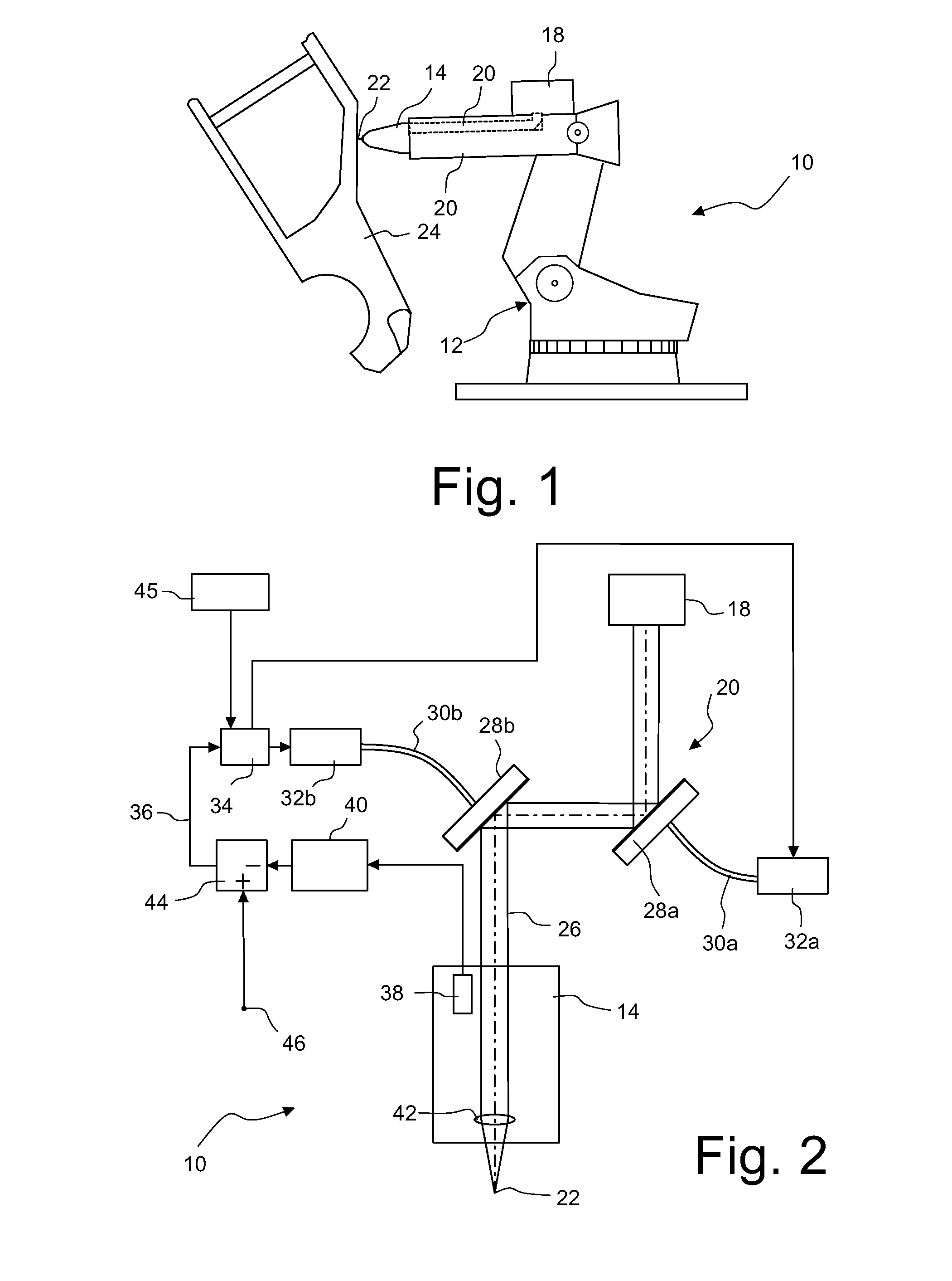
[0042]FIG. 1 shows a side view of a laser processing apparatus 10 having a robot 12 and a processing head 14 which is fastened to a movable arm 16 of the robot 12.

[0043]The laser processing apparatus 10 additionally includes a laser radiation source 18, which in the exemplary embodiment shown is in the form of an Nd:YAG laser or CO2 laser. Other lasers and other arrangements of the laser radiation source 18 relative to the robot 12 are of course likewise possible. The laser radiation generated by the laser radiation source 18 is guided via a laser guidance system 20 to the processing head 14 and from there is focused in a focal spot 22. The arm 16 of the robot 12 is positioned with respect to a workpiece 24 in such a manner that the focal spot 22 is situated at the desired location on the workpiece 24 and the workpiece 24 can be processed by welding, separating or in another manner.

1. Beam Guidance System

[0044]FIG. 2 shows schematically the beam path of the laser radiation as well a...


PUM

PropertyMeasurementUnit
diameteraaaaaaaaaa
angleaaaaaaaaaa
stiffnessaaaaaaaaaa

Abstract

An adaptive mirror for a laser processing apparatus has a housing and a pressure chamber which is arranged in the housing and can be connected to a pressure source. A mirror substrate, which delimits the pressure chamber, is fixedly clamped in the housing. Depending on the internal pressure in the pressure chamber, which can be changed by means of the pressure source, the mirror substrate is deformed. The mirror substrate has a stiffness which increases towards the geometric centre at least in a region surrounding the geometric centre of the mirror substrate. By means of such a stiffness distribution, an almost spherical deformation can be achieved over a large surface of the mirror substrate despite the mirror substrate's being fixedly clamped into the housing.

Description

BACKGROUND OF THE INVENTION[0001]1. Field of the Invention[0002]The invention relates to an adaptive mirror for a laser processing apparatus with which workpieces can be welded, cut or otherwise processed.[0003]2. Description of the Prior Art[0004]A laser processing apparatus conventionally comprises a laser radiation source, which can be, for example, an Nd:YAG laser, a fibre laser, a disk laser or a CO2 laser. A laser processing apparatus further includes a processing head, which focuses the laser radiation generated by the laser radiation source in a focal spot. A beam guidance system guides the laser radiation generated by the laser radiation source to the processing head. Especially when the laser radiation has a relatively lower beam quality, it is generally guided to the processing head as a collimated beam with a relatively large diameter (20 mm to 100 mm). For deflecting the laser radiation, deflecting mirrors with planar or curved surfaces are mostly provided. The processi...

Claims


Application Information

Patent Timeline
Patent Type & Authority Applications(United States)
IPC IPC(8): G02B26/08B23K26/04G02B7/182
CPCG02B26/0825B23K26/046G02B7/182B23K26/0643B23K26/0884G02B27/0911G02B27/0983
Inventor BISCHOF, DIETMAR
Owner LT ULTRA PRECISION TECH
Why Eureka
Try Eureka