Rapid charging power supply system

a power supply system and rapid charging technology, applied in the direction of battery/fuel cell control arrangement, secondary cell servicing/maintenance, capacitor propulsion, etc., can solve the problems of long low operation rate, and electric vehicles corresponding to the charging method according to patent literature 2 are not equipped with rapid charging control means, etc., to improve the utilization efficiency of charging facilities, shorten the waiting time for charging, and the effect of length

Inactive Publication Date: 2014-11-27
INST FOR ENERGY APPL TECH
View PDF11 Cites 52 Cited by
  • Summary
  • Abstract
  • Description
  • Claims
  • Application Information

AI Technical Summary

Benefits of technology

[0016]According to the invention defined by claim 1, the rapid charging power supply system has a power supply switching means for switching and supplying the DC power output from the stationary rapid charger, which makes it possible to rapidly charge each of a first electric moving body equipped with a rapid-charging control means, and a second electric moving body which is not equipped with the rapid-charging control means, by using a single stationary rapid charger. As a result, even if such a traffic society comes to exist in which the first electric moving body and the second electric moving body of different charging methods are mixed and used, it becomes possible to perform rapid charging on the respective electric moving bodies smoothly without causing confusion.
[0017]In addition, according to the invention defined by claim 1, the power feeding control means discontinues power feeding from the stationary rapid charger to the stationary electric storage means during charging of the electric storage means of the first electric moving body with the DC power output from the stationary electric storage means. Thus, if the power supply is a commercial AC power supply, rapid charging can be performed on the first electric moving body with only the electric power stored in the stationary electric storage means without causing excessive burden on energy transmission and distribution systems of electric power companies. Accordingly, upon rapid charging using the first charging circuit, maximum electric power required by the rapid charging of the first electric moving body can be supplied at once from the stationary electric storage means to the first electric moving body, which makes it possible to perform ultrahigh speed charging. As a result, it becomes possible to perform rapid charging on the first electric moving body with a similar length of time required for fueling gasoline automobiles. This shortens time to wait for charging and improves utilization efficiency of the charging facilities.
[0018]According to the invention defined by claim 2, a part of the electric power stored in the stationary electric storage means is usable for rapid charging of the on-vehicle electric storage means of the second electric moving body through the stationary rapid charger. Thus, even in a case of rapid charging of the second electric moving body at peak hour, for example, for the need for electric power, it becomes possible to avoid placing a great burden on the energy transmission and distribution system.
[0019]According to the invention defined by claim 3, the stationary electric storage means is connected with an inverter for converting DC power into AC power and supplying the converted AC power to a commercial electric power system. Thus, it becomes possible to supply the electric power stored in the stationary electric storage means to the commercial electric power system, thereby leveling electric power load.
[0020]According to the invention defined by claim 4, the stationary rapid charger is capable of supplying DC power in which neither a voltage nor a current is controlled for rapid charging. Thus, even if the first electric moving body is connected to the second charging circuit, it becomes possible to perform rapid charging on the first electric moving body by using the rapid-charging control means of the first electric moving body.
[0021]According to the invention defined by claim 5, the first electric moving body has a power converter for converting AC power from a commercial AC power supply or a non-contact power feeding means connected to the stationary electric storage means side into DC power, and the rapid-charging control means is connected with an output side of the power converter. Thus, operations for connecting the charging connector will not be necessary, thereby significantly reducing labor for the charging operation.

Problems solved by technology

However, the electric vehicle corresponding to the charging method according to Patent Literature 2 is not equipped with a rapid-charging control means.
Thus, according to this method, one stationary rapid charger can only rapidly charge one vehicle, thus causing a problem of creating a long waiting time for charging.
In addition, since electric vehicles are not currently fully widespread, the stationary rapid charger according to Patent Literature 2 is not frequently used, causing a problem of low operation rates.

Method used


Image

  • Rapid charging power supply system
  • Rapid charging power supply system
  • Rapid charging power supply system

Examples


embodiment 1

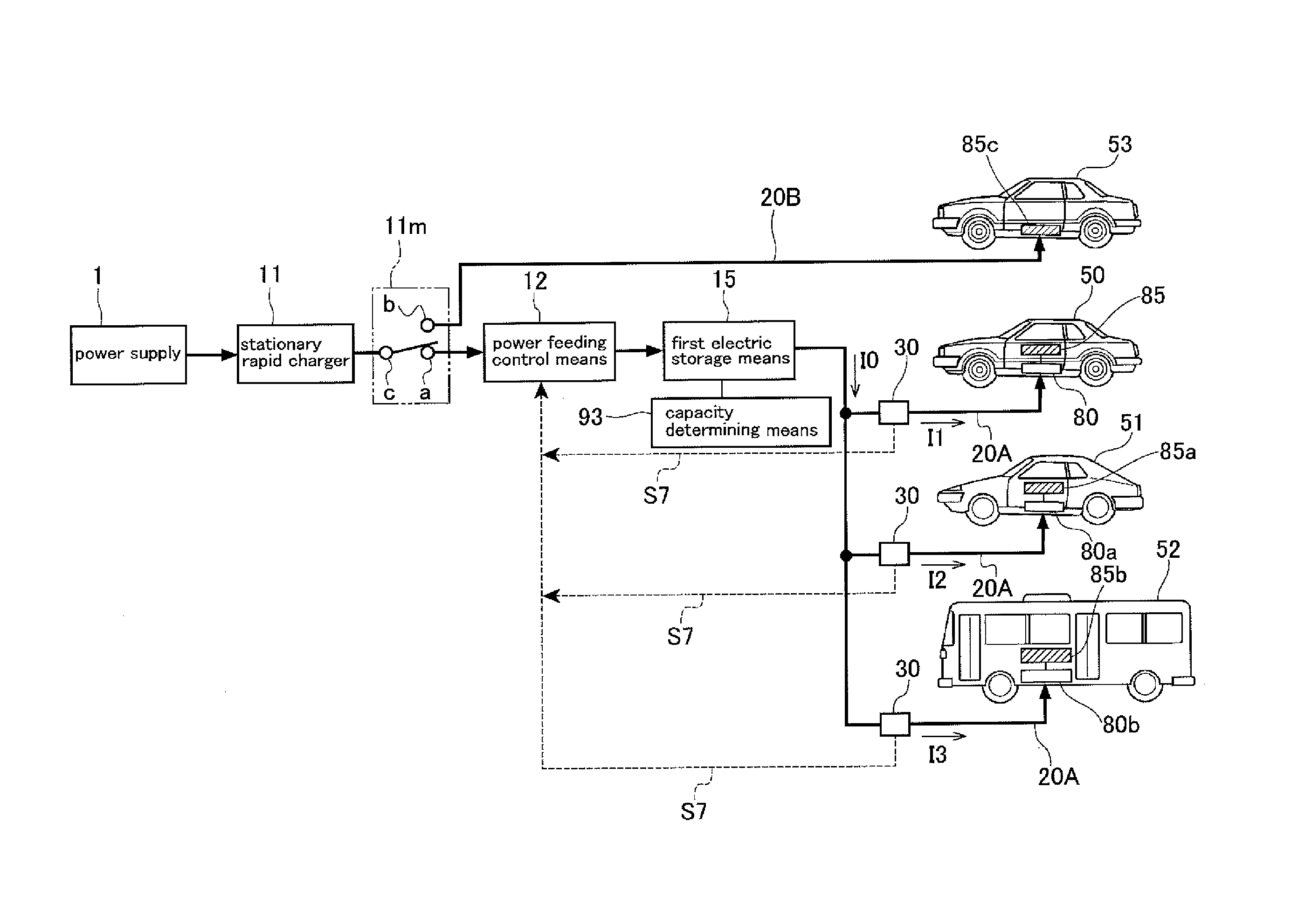
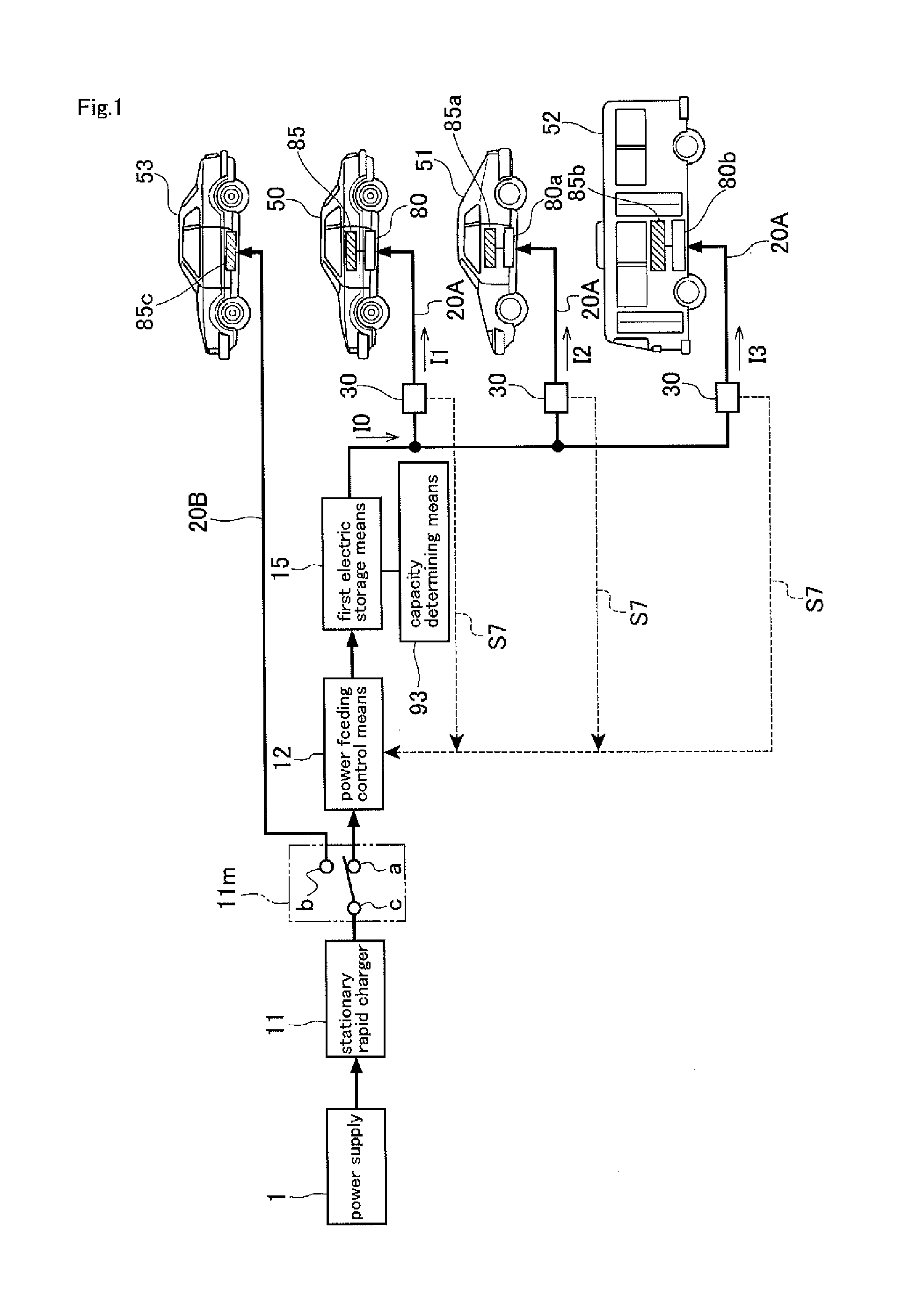
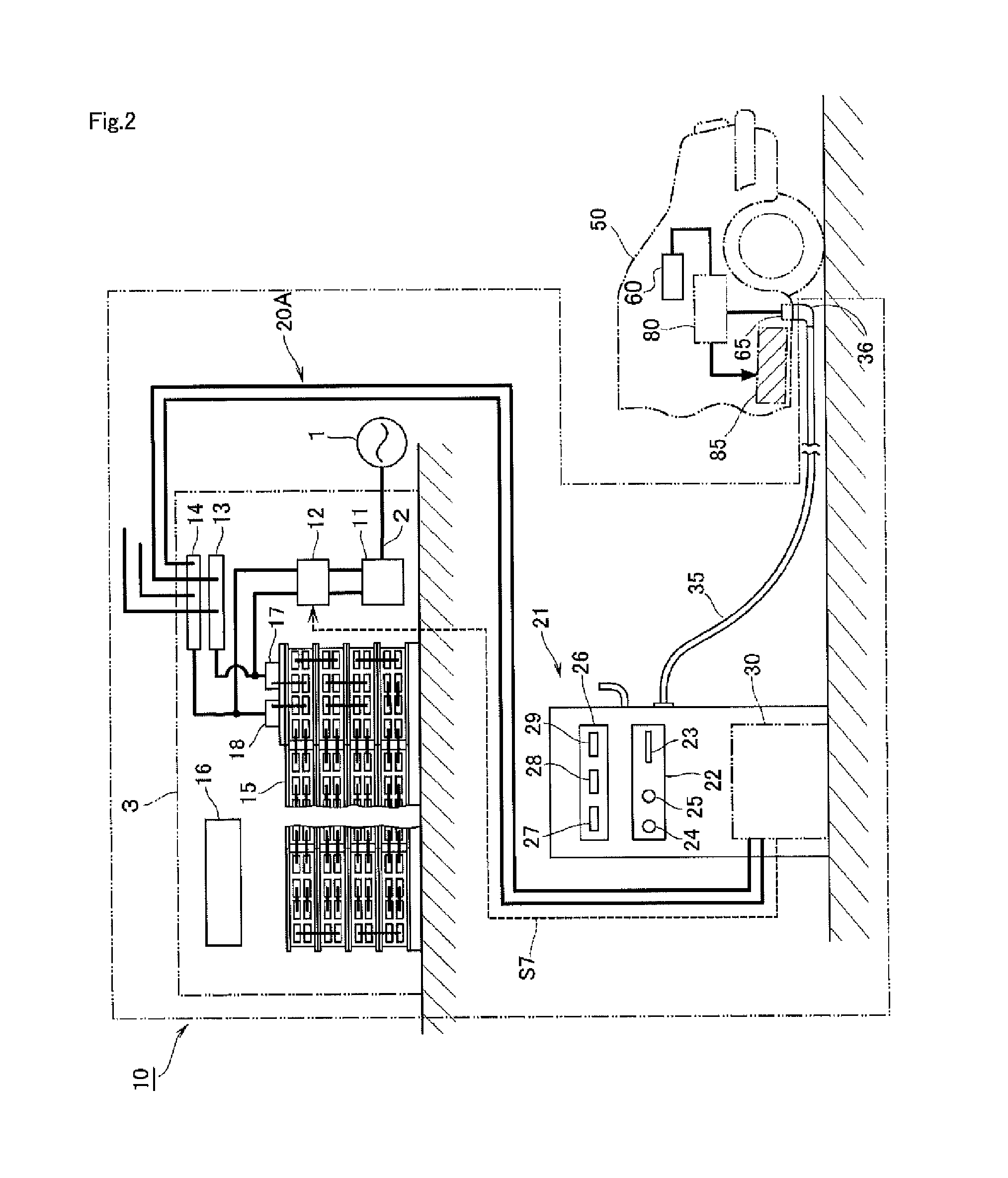
[0046]FIGS. 1 to 10 show Embodiment 1 according to the present invention. In FIG. 2, reference numeral 1 indicates a commercial AC power supply as a power source, and a three-phase AC power supply, for example, is used as an AC power supply 1. Power from the AC power supply 1 is supplied into a building 3 through an electric power line 2. Within the building 3, there are a stationary rapid charger 11, a power supply switching means 11m, a power feeding control means 12, a first electric storage means 15 functioning as a stationary electric storage means, and other devices, which constitute a rapid charging power supply system 10. The input side of the stationary rapid charger 11 is connected to the electric power line 2 within the building 3. The stationary rapid charger 11 has a function of regulating three-phase AC power from the electric power line 2 to a predetermined voltage value, and converting it into DC power.

[0047]The output side of the stationary rapid charger 11 is conne...

embodiment 2

[0085]FIG. 11 shows Embodiment 2 according to the present invention, showing a case of application for rapid charging of both a vehicle and a ship which function as electric moving bodies. The difference in Embodiment 2 from Embodiment 1 is the difference in the type of the electric moving bodies, and the remaining parts correspond to Embodiment 1. Accordingly, the same reference numerals as those in Embodiment 1 are denoted for the corresponding parts, thus omitting the description with respect to the corresponding parts. The same applies to other embodiments to be described below.

[0086]As shown in FIG. 11, the respective charging circuits 20A, connected in parallel with the first electric storage means 15, are connected with a vehicle 50, an electric boat 100, and a passenger ship 101. Electric power for rapid charging is suppliable to the second electric storage means 85 of the vehicle 50, to the second electric storage means 85d of the electric boat 100, and to the second electr...

embodiment 3

[0087]FIG. 12 shows Embodiment 3 according to the present invention, showing an alternate embodiment of Embodiment 1. A wind power generator 5 or a solar cell 6 is excellent for environment since such generation does not produce CO2 during the generation of electric power. However, such wind power generation and solar power generation are susceptible to weather, and the output is greatly varied, thus having a problem of being difficult to be in cooperation with electric power systems. In Embodiment 3, electric power from a wind power generator 5 or a solar cell 6 with large output variation is stored in a first electric storage means 15 functioning as a stationary electric storage means, and the stored electric power is used to perform rapid charging on vehicle 50. With regard to the first electric storage means 15, it is desirable to select a most suitable type in consideration of the fact that electric power supplied will greatly vary. Furthermore, as shown in FIG. 12, it is also ...


PUM


Abstract

A rapid charging power supply system comprises: a stationary rapid charger (11) for controlling power supplied from a power supply (1) to be a DC power optimum for rapidly charging an on-vehicle electric storage means (85c) equipped in a second electric moving body (53); a power supply switching means (11m) for switching and supplying the DC power from the stationary rapid charger (11) to either a first charging circuit (20A) for supplying the DC power to a first electric moving vehicle (50) or a second charging circuit (20B) for supplying the DC power to the second electric moving body (53); an stationary electric storage means (15) capable of storing DC power charged by the DC power supplied to the side of the first charging circuit (20A) from the stationary rapid charger (11) via the power supply switching means (11m) and used for being directly supplied to at least the first electric moving body (50); and a power feeding control means (12) for stopping power supply to the stationary electric storage means (15) from the stationary rapid charger (11) when charging an on-vehicle electric storage means (85) of the first electric moving body (50) by the DC power output from the stationary electric storage means (15).

Description

TECHNICAL FIELD[0001]The present invention is directed to a rapid charging power supply system capable of rapidly charging an electric moving body, such as a vehicle and a ship, and in particular, the present invention is directed to a rapid charging power supply system capable of rapidly charging each of two electric moving bodies of different charging methods.BACKGROUND ART[0002]While electric vehicles are excellent from an environmental point of view since they do not release exhaust gas, they have a problem of requiring a relatively long period of time for charging. In order to shorten the charging time, it is necessary to supply a large amount of electric power in a short period of time to electric vehicles; and it is necessary for an area in which only low voltage power lines are laid to increase the power reception capacity of the electric power facilities. Accordingly, there is a technique known to rectify commercial AC power, to store DC power in a large-size storage batter...

Claims


Application Information

Patent Timeline
Patent Type & Authority Applications(United States)
IPC IPC(8): B60L11/18H02J3/32H02J7/00H02J7/02H02J7/34
CPCB60L11/1816H02J2007/0095B60L11/1811B60L11/182H01M10/44H02J7/02B60L1/003B60L2210/10B60L2210/30B60L2210/40B60L2240/34Y02T90/14Y04S10/126Y04S30/14B60L2200/26B60L53/16B60L50/40B60L50/52B60L53/30B60L53/31B60L53/36B60L53/64B60L55/00B60L53/63B60L53/65B60L53/11B60L58/22B60L53/305H02J7/342B60L50/60B60L53/122B60L53/126H02J2310/48Y02E60/00Y02T10/70Y02T10/7072Y02T10/72Y02T90/12Y02T90/167Y02T90/16Y02E60/10H02J7/0014H02J3/322H02J2310/42H02J7/0042B60L53/12H02J50/12B60L50/50
Inventor SUGANO, TOMIO
Owner INST FOR ENERGY APPL TECH
Why Eureka
Try Eureka