Supercharge Your Innovation With Domain-Expert AI Agents!

Light-emitting diode lighting apparatus having multifunctional heat sink flange

a lighting apparatus and light-emitting diode technology, applied in the direction of lighting and heating apparatus, electric lighting with batteries, fixed installation, etc., can solve the problems of obstructing environmental protection, wasting resources, and high power consumption of fluorescent electric lamps, so as to reduce the weight and a size of the product, improve usability and compatibility of led lighting apparatus, and reduce the cost of producing various lighting lamps using led lighting apparatus

Inactive Publication Date: 2014-11-27
AHN IN KYU +1
View PDF27 Cites 26 Cited by
  • Summary
  • Abstract
  • Description
  • Claims
  • Application Information

AI Technical Summary

Benefits of technology

The present invention proposes an LED lighting apparatus with a multifunctional heat sink flange. This flange is formed along the outer edge of the main heat sink to which the LED board is fixed, and it has alternating rows of holes to widen the heat dissipation area and improve heat dissipation performance and light efficiency. The heat sink flange can also accommodate various heat sink segments to change the heat dissipation area based on the amount of heat generated from the LEDs. Additionally, the heat sink flange allows for the installation of various structures and components such as protective cages, anti-dropping gaddets, and color presentation plates, which improves usability and compatibility and reduces production costs.

Problems solved by technology

Such incandescent or fluorescent electric lamps have high power consumption, waste resources, obstruct environmental protection, and increase an environmental temperature to negatively influence the lamp's service time due to the easy generation of heat.
Due to high photoelectric conversion efficiency, the LED has very low power consumption and a resultant low generation of heat.
However, the LED has a problem in that heat generated when an LED chip is driven exerts an influence on brightness and service time.
However, the heat dissipation effect can be restrictively produced, which cannot be said to be preferable.
When a main body of the case integrated with the heat dissipation fins is formed using the die for die casting, the aluminum case main body and heat dissipation fins cannot be formed to be thin.
As such, it is impossible to reduce weight of a product and to maximize a heat dissipation area.
Further, the heat generated when the LEDs are driven cannot be effectively radiated.
As a result, it is very difficult to form a boss for detachably installing an upper cover or a transparent cap in the narrow space.
As such, there is a limitation in a reduction in weight.
Further, when a short circuit occurs between a power supply for supplying power to the LEDs and the metallic main body, there is a possibility of electric shock.
Thus, to resolve this problem with insulation, in some cases, the power supply itself is formed in an expensive insulation type device.
This leads to increasing a production cost of products.
This also increases the production cost.
However, despite that the amount of generated heat is different depending on the number of LEDs installed on the LED board, the heat sink used for most of the conventional lighting modules including the lighting module having the aforementioned configuration and conventional lighting apparatuses is not provided with any structure capable of changing a critical capacity of dissipated heat according to the number of installed LEDs, i.e. does never provide changeability of the amount of generated heat with respect to different lighting capacities as well as compatibility of the heat sink itself.
As such, the production cost of a product is increased.
However, no configuration capable of being selectively coupled with the structure regardless of the shape or purpose of the structure when used is provided.

Method used


Image

  • Light-emitting diode lighting apparatus having multifunctional heat sink flange
  • Light-emitting diode lighting apparatus having multifunctional heat sink flange
  • Light-emitting diode lighting apparatus having multifunctional heat sink flange

Examples


Embodiment Construction

[0066]Reference will now be made in greater detail to an exemplary embodiment of the invention with reference to the accompanying drawings.

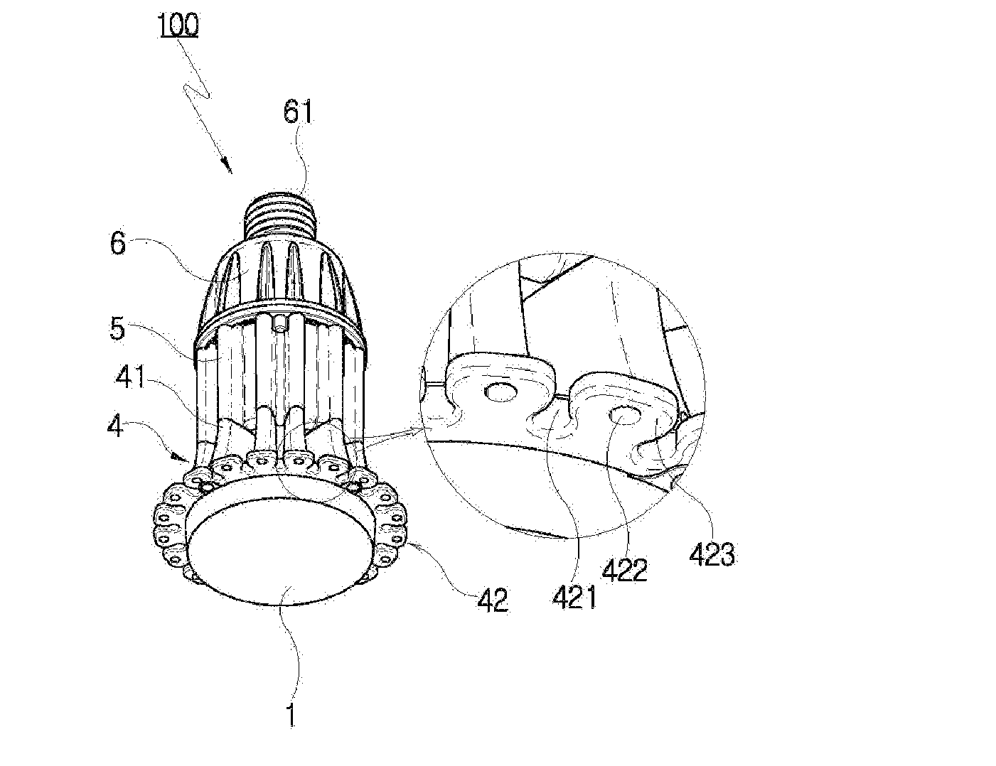
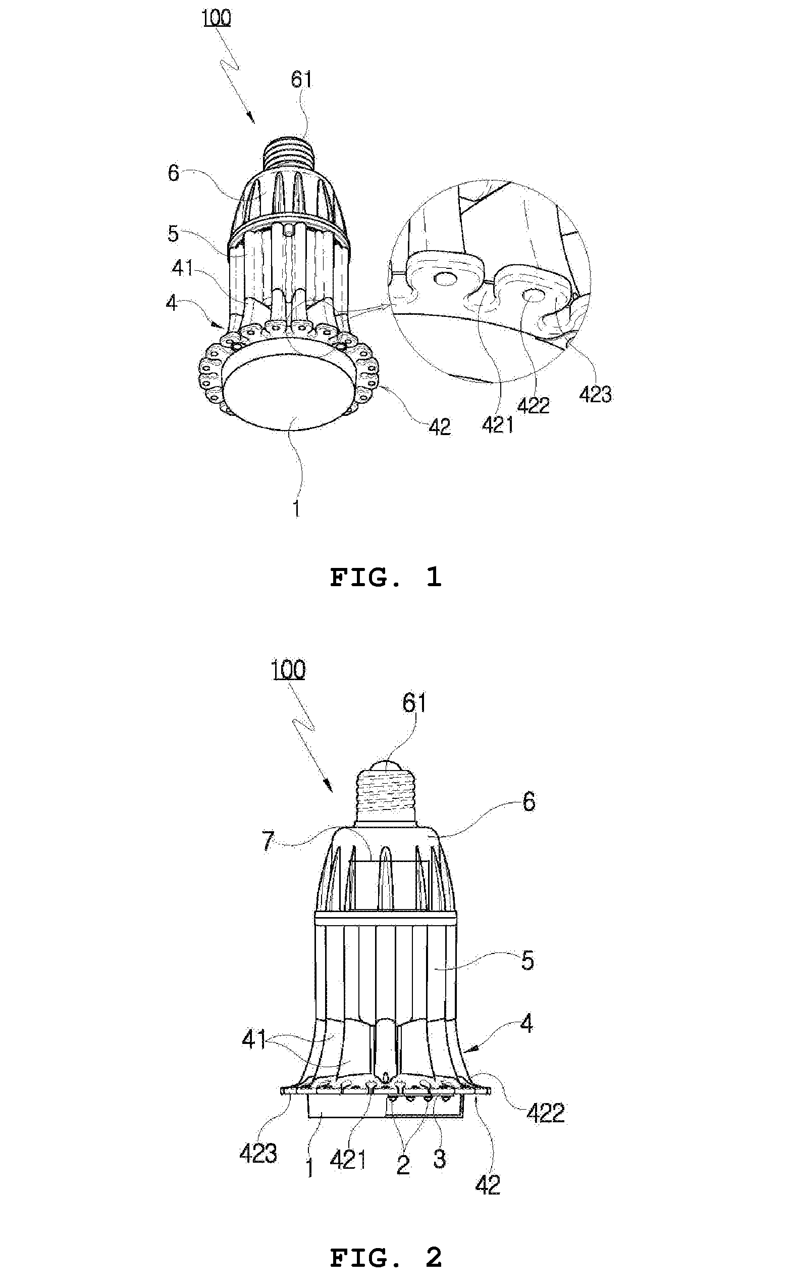
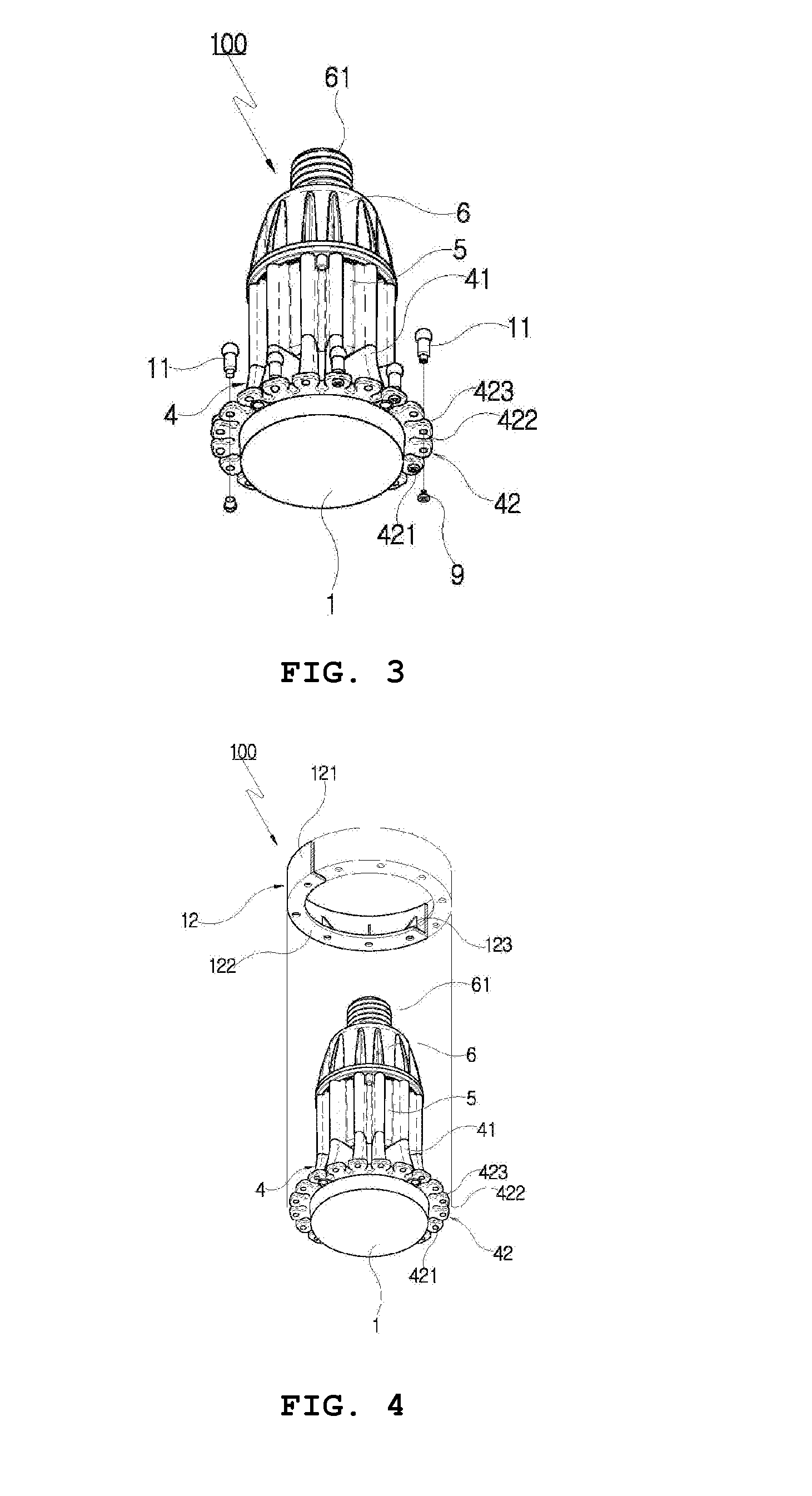
[0067]FIG. 1 is a perspective view showing a light-emitting diode (LED) lighting apparatus having a multifunctional heat sink flange according to the present invention. FIG. 2 is a partial cutaway front view showing the LED lighting apparatus having a multifunctional heat sink flange according to the present invention. FIG. 3 is a partial exploded perspective view showing a state in which heat sink segments are further installed on the LED lighting apparatus having a multifunctional heat sink flange according to the present invention. FIG. 4 is an exploded perspective view showing an embodiment of a heat sink ring applied to the LED lighting apparatus having a multifunctional heat sink flange according to the present invention. FIG. 5 is a perspective view showing another embodiment of a heat sink ring applied to the LED lighting apparatus having...


PUM


Abstract

Disclosed is a light-emitting diode (LED) lighting apparatus having a multifunctional heat sink flange, which includes an LED board on which a transmitted light cap and a plurality of LEDs are mounted, a main heat sink formed of magnesium or an magnesium alloy, an auxiliary heat sink formed of a conductive / polymeric resin material for heat dissipation, a heat sink upper case formed of a conductive / polymeric resin material for heat dissipation, and a power supply. The main heat sink includes multiple streamlined heat sink segments that are integrally formed on an outer surface thereof so as to radially protrude to allow air to flow in all directions, and a heat sink flange formed along an outer circumference of a bottom thereof such that omega-shaped wings having enclosed holes and inverse omega-shaped open holes are alternately formed.

Description

BACKGROUND OF THE INVENTION[0001]1. Field of the Invention[0002]The present invention relates, in general, to a light-emitting diode (LED) lighting apparatus having a multifunctional heat sink flange, and, more particularly, to an LED lighting apparatus having an electric lamp type device or a modular type device, in which: a heat sink flange is further formed along an outer circumference of the bottom of a main heat sink to which a LED board is directly fixed such that omega-shaped wings having enclosed holes and approximately inverse omega-shaped open holes are alternately formed as means for widening a heat dissipation area of the main heat sink; heat sink segments formed in various shapes such as a rod shape and a heat sink ring separately formed in various shapes such as a cylindrical shape can be removably installed in correspondence with a change in amount of heat generated from the LEDs installed on the LED board; and various structures (e.g., when the LED lighting apparatus...

Claims


Application Information

Patent Timeline
Patent Type & Authority Applications(United States)
IPC IPC(8): F21V29/00F21S8/00F21L4/00
CPCF21V29/2243F21L4/00F21V29/24F21V29/2293F21S8/00F21S8/036F21S8/063F21S8/08F21V5/06F21V15/02F21V17/12F21V29/713F21V29/773F21V29/85F21V29/87F21V29/89F21V29/70
Inventor AHN, IN-KYULEE, SEUL-KI
Owner AHN IN KYU
Features
  • R&D
  • Intellectual Property
  • Life Sciences
  • Materials
  • Tech Scout
  • Unparalleled Data Quality
  • Higher Quality Content
  • 60% Fewer Hallucinations
Learn More