Air driven reductant dosing system
- Summary
- Abstract
- Description
- Claims
- Application Information
AI Technical Summary
Benefits of technology
Problems solved by technology
Method used
Image
Examples
Embodiment Construction
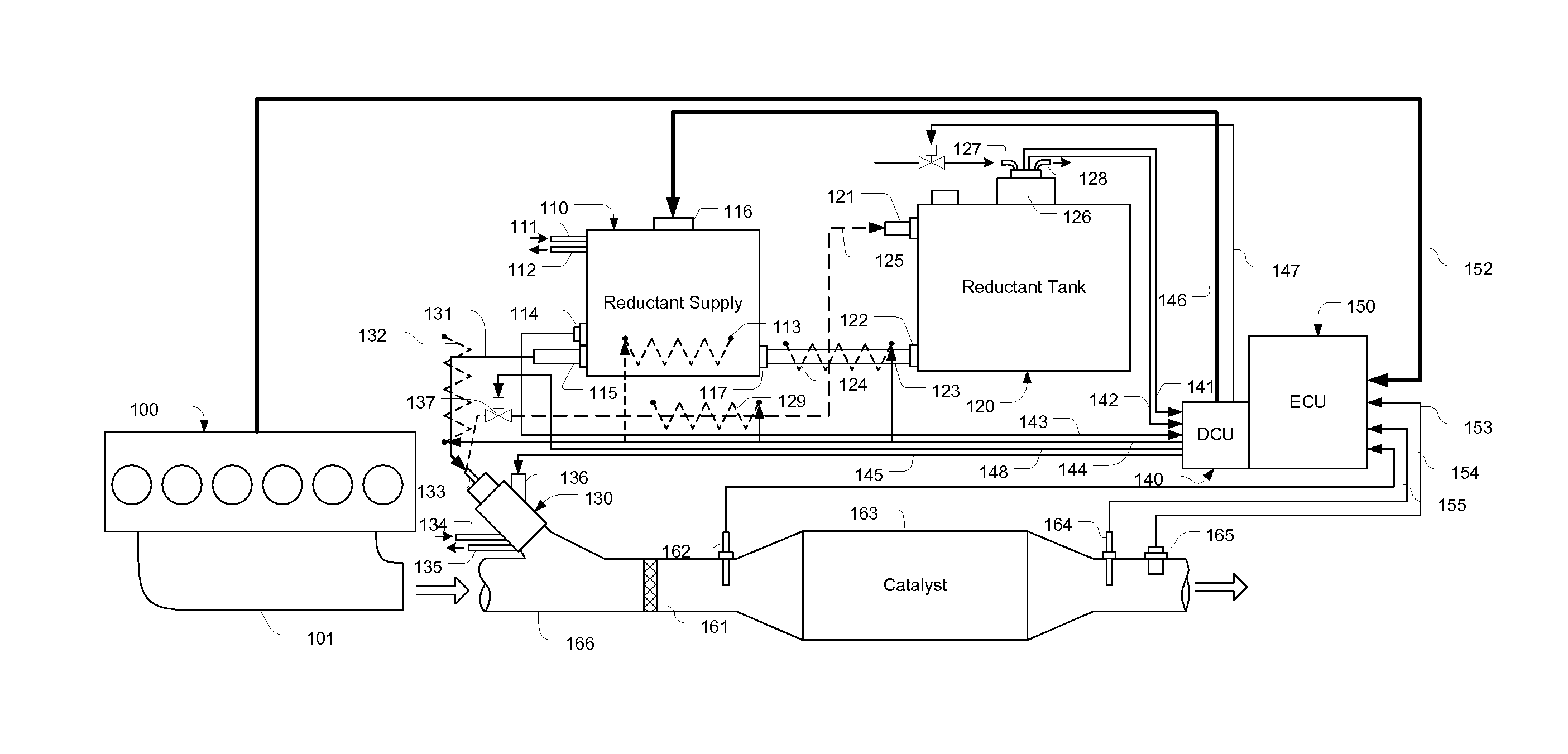
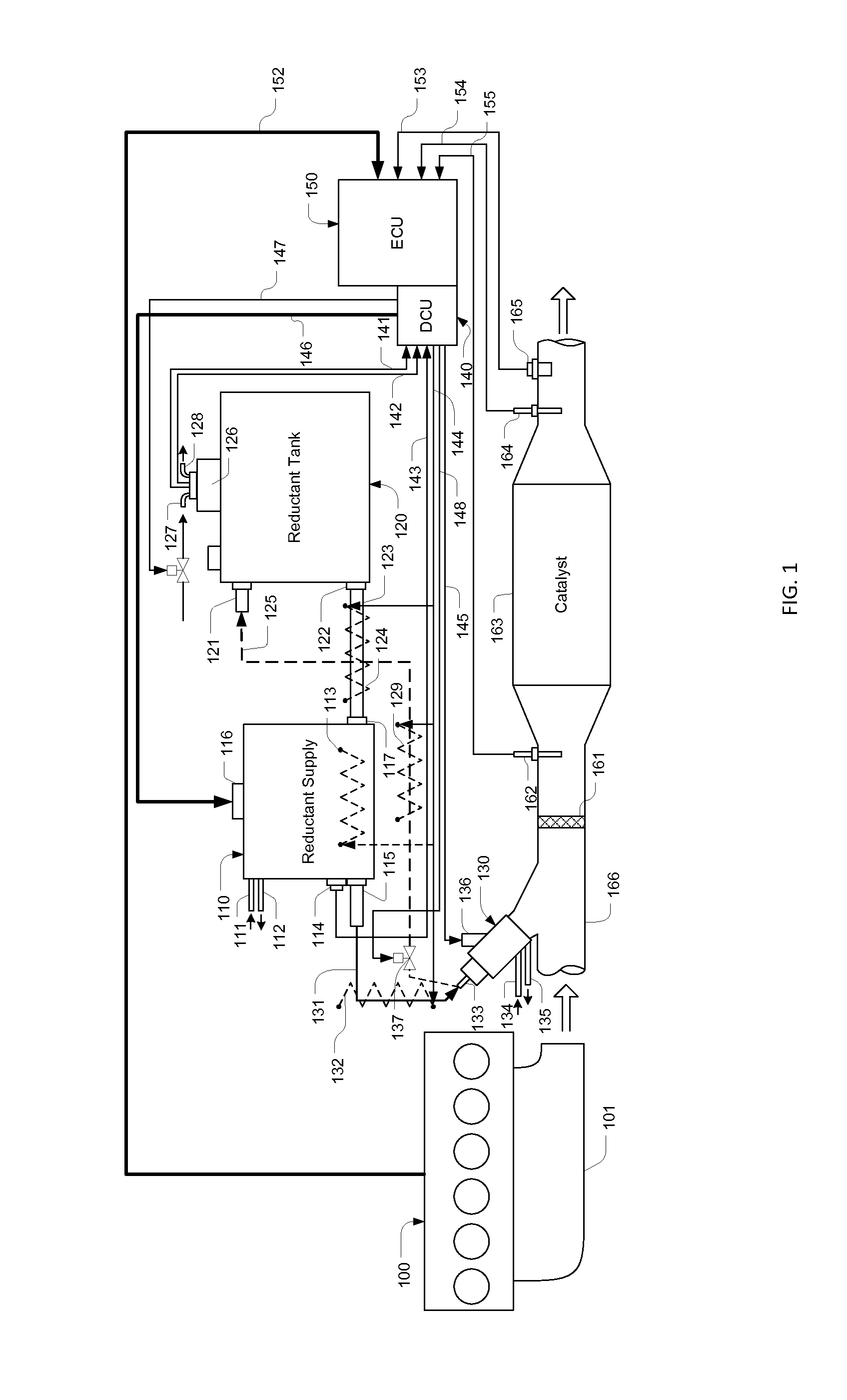
[0038]Referring to FIG. 1, in an engine aftertreatment system, exhaust gas generated by an engine 100 enters a passage 166 through a manifold 101. On the passage 166, a reductant injector 130 is installed. The solenoid valve of the injector 130 is controlled by a Dosing Control Unit (DCU) 140 through signal lines 145 connected to a port 136. And reductant is provided by a redutant supply module 110 through a pressure line 131 fluidly connected to a port 133. To avoid damages caused by high temperature exhaust gas, engine coolant is cycled from an inlet port 134 to an outlet port 135. The reductant injected from the injector 130 mixes with exhaust gas, and through a mixer and diffuser 161, the result gas enters a catalyst 163, where SCR reactions reduce NOx in the exhaust gas.
[0039]The reductant supply module 110 has a port 115 fluidly connected to the port 133 of the injector 130 with the line 131 for providing pressurized reductant supply to the injector. A pressure sensor (not sho...
PUM
 Abstract
Description
Claims
Application Information
 - R&D
- Intellectual Property
- Life Sciences
- Materials
- Tech Scout
- Unparalleled Data Quality
- Higher Quality Content
- 60% Fewer Hallucinations
Browse by: Latest US Patents, China's latest patents, Technical Efficacy Thesaurus, Application Domain, Technology Topic, Popular Technical Reports.
© 2025 PatSnap. All rights reserved.Legal|Privacy policy|Modern Slavery Act Transparency Statement|Sitemap|About US| Contact US: help@patsnap.com


