
System and Method for Sequential Injection of Reagent to Reduce NOx from Combustion Sources

a technology of nox and reagents, which is applied in the field of sequential injection of reagents to reduce nox from combustion sources, can solve the problem of short duration of reagent injection into the duct, and achieve the effect of reducing the time of nox injection

Active Publication Date: 2014-12-11
CECO ENVIRONMENTAL IP INC
View PDF13 Cites 27 Cited by
  • Summary
  • Abstract
  • Description
  • Claims
  • Application Information

AI Technical Summary

Benefits of technology

The present invention relates to a design for a combustion source that reduces pollutant emissions by injecting reagent into the exhaust gases and allowing it to decompose across a downstream catalyst. The invention solves problems associated with previous designs where imbalances in reagent injection into the duct tended to balance out over time. The invention includes multiple injectors positioned around the duct, which are electronically sequenced in and out of service to minimize any imbalance in reagent injection. The injectors are operated in an alternating sequence, and the reagent is allowed to decompose and react across the downstream catalyst to reduce pollutant emissions. The technical effect of the invention is to minimize pollutant emissions from a lean burn combustion source.

Problems solved by technology

Thus, any imbalance in reagent injection into the duct is of very short duration and the reagent concentration in the duct tends to balance out at the downstream catalyst face.

Method used


Image

  • System and Method for Sequential Injection of Reagent to Reduce NOx from Combustion Sources
  • System and Method for Sequential Injection of Reagent to Reduce NOx from Combustion Sources
  • System and Method for Sequential Injection of Reagent to Reduce NOx from Combustion Sources

Examples


Embodiment Construction

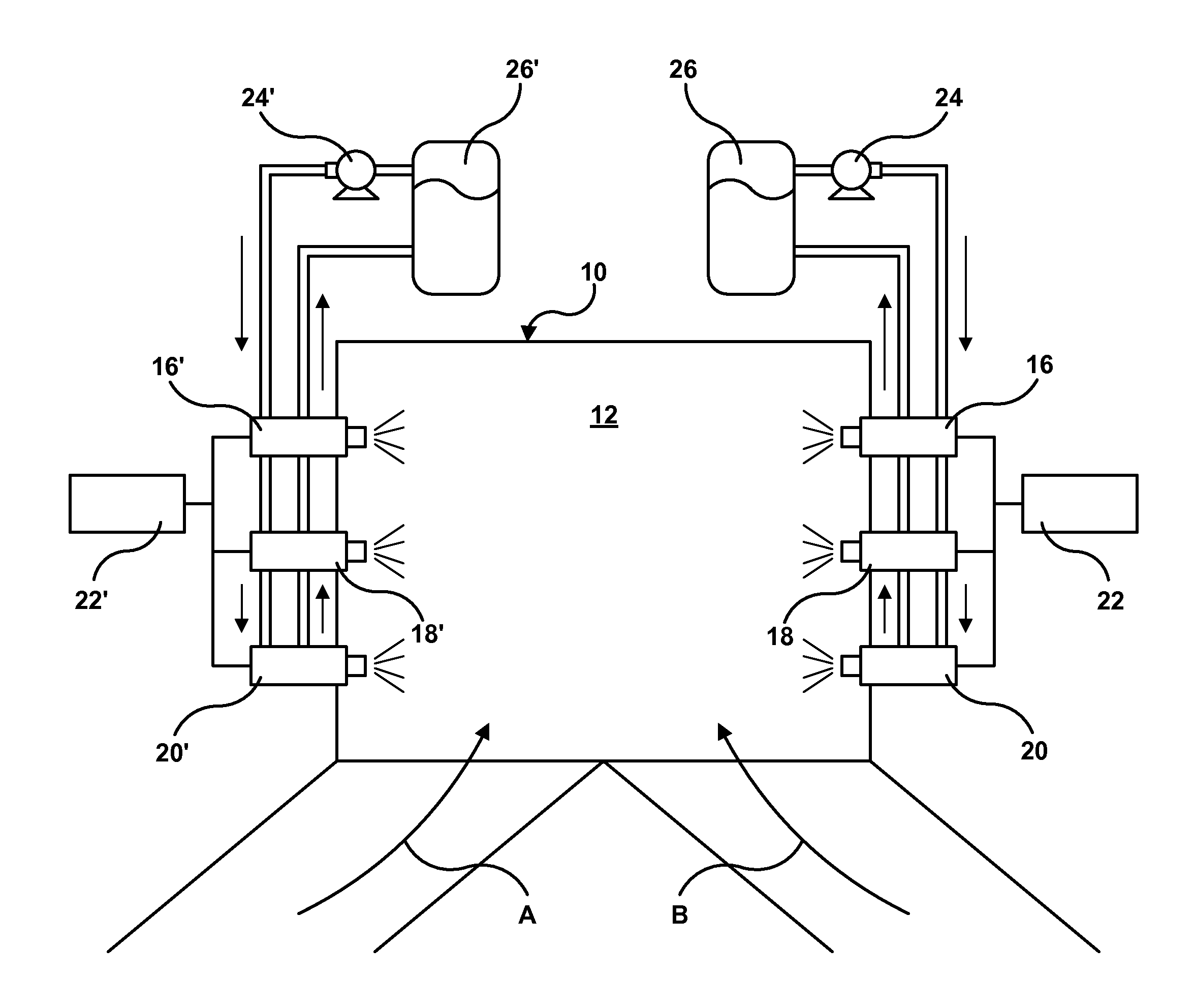
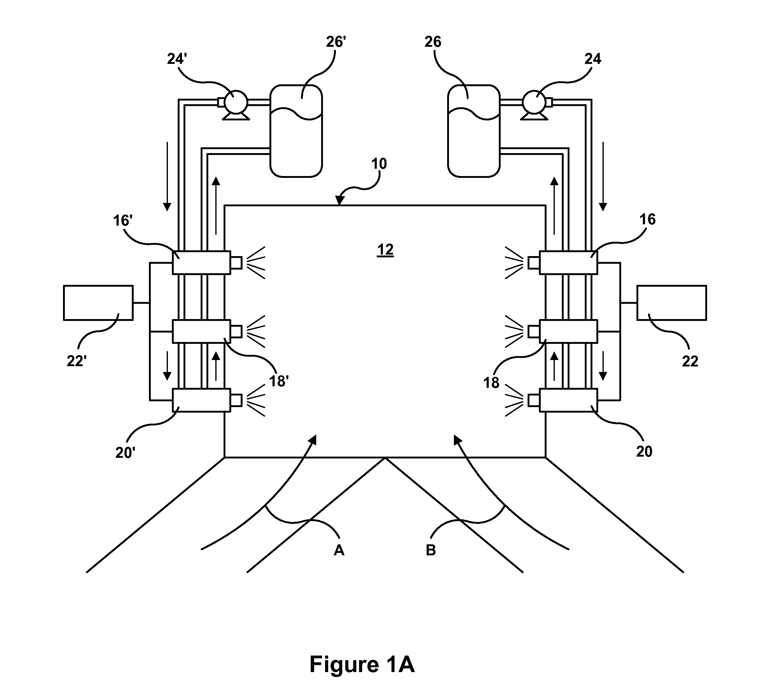
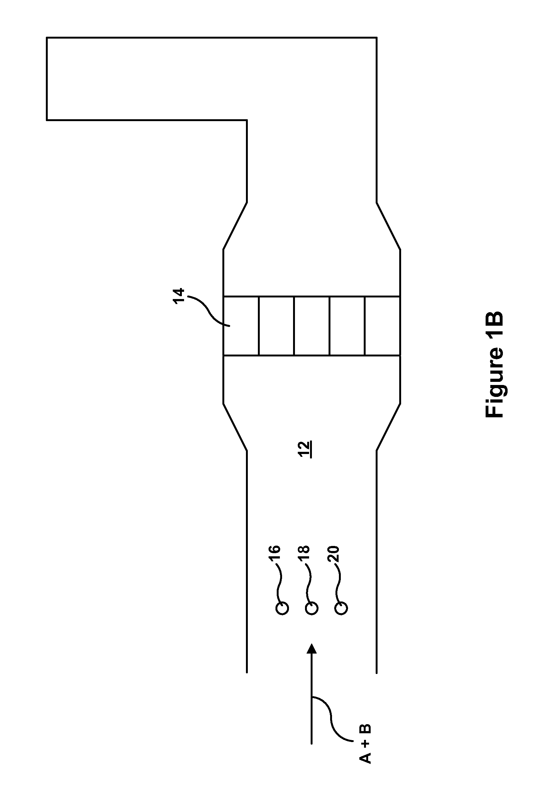
[0031]Referring first to FIGS. 1A and 1B, an exemplary embodiment of a system (10) for reducing NOx emissions from a lean burn combustion source configured in accordance with the present invention includes a common duct (12), which is fed with exhaust gases (indicated by arrows A and B) from two identical 55,000 pph natural gas fired boilers (not shown). A common SCR catalyst (14) is placed in the duct (12) at a distance downstream from where the two boiler outlets (shown in the vicinity of arrows A and B in FIG. 1A) combine into the common duct (12).

[0032]A water based urea solution is injected into the duct (12) at a rate sufficient to reduce the NOx emissions across the catalyst (14) by a predetermined amount using six solenoid actuated injectors (16, 16′, 18, 18′, 20, 20′) CFD modeling is used to predict where on the exhaust duct (12) the six injectors (16, 16′, 18, 18′, 20, 20′) should be located as described in commonly owned U.S. Patent Application Publication No. US 2014 / 009...


PUM


Abstract

In a large exhaust duct from a lean burn combustion source, such as a boiler, diesel engine or gas turbine, multiple injectors can be used to inject a reagent, such as an aqueous solution of urea or ammonia, into the exhaust for use in the catalytic reduction of NOx in a process known in the art as selective catalytic reduction (SCR). When operating at low injection rates, such as during low combustor loads, the injectors are operated individually for short periods of time in a sequential manner.

Description

FIELD OF THE INVENTION[0001]The present invention relates generally to a method for reducing nitrogen oxide (“NOx”) emissions from a lean burn combustor equipped with a NOx reducing exhaust catalyst, and more specifically to a such a method involving the operation of a plurality of reagent injectors in an off / on sequential manner to supply low flow rates of reagent corresponding to low loads or low NOx reduction requirements for the combustor.BACKGROUND OF THE INVENTION[0002]The art for the reduction of NOx from lean burn combustion sources has found the injection of ammonia or urea into exhaust ducts and flues upstream of a selective catalytic reduction (SCR) catalyst to be a solution to the issue of NOx emissions from diesel engines, gas turbines, boilers and the like. Urea, while a preferred reagent for SCR due to its safety and handling characteristics compared to ammonia, generally requires complicated and costly urea decomposition schemes directed at converting the aqueous ure...

Claims


Application Information

Patent Timeline
IPC IPC(8): F01N3/20
CPCF01N3/208F01N2610/02F01N2900/1404F01N2900/1411F01N2900/1812Y02T10/12
Inventor BRODERICK, JEFFREY MICHAELLINDEMANN, SCOTT H.LINDEMANN, ERICVALENTINE, JAMES M.
Owner CECO ENVIRONMENTAL IP INC
Learn More