Bottle Chamber Gas Lift Systems, Apparatuses, and Methods Thereof

a gas lift and bottle chamber technology, applied in the direction of non-positive displacement pumps, borehole/well accessories, constructions, etc., can solve the problems of mechanical fatigue and failure of moving parts, high maintenance and repair costs, and uneconomic operation of gas and/or oil wells

Active Publication Date: 2014-12-11
LUFKIN GEARS LLC
View PDF7 Cites 0 Cited by
  • Summary
  • Abstract
  • Description
  • Claims
  • Application Information

AI Technical Summary

Benefits of technology

[0019]Applicants have created systems, methods, and apparatuses for increasing the production of a gas well. The system can include a controller and upper and lower portions. The upper portion can include an injection valve for regulating the amount of a first gas injected into an injection conduit. The lower portion can include a chamber valve for regulating the flow of a first gas through an upper tubing string and a vent valve for regulating the flow of the second gas and a standing valve. The collected fluid creates pressure in the lower portion causing the second gas to flow through the annulus to the surface. The controller controls the injection valve and is coupled to a pressure gauge for measuring pressure in the lower portion. With the aid of this system, well operators can increase production of gas well formations without increasing backpressure on those formations.
[0033]As used herein, the term “annulus” refers to any void space in an oil well between any piping, tubing or casing and the piping, tubing or casing immediately surrounding it. The presence of an annulus gives the ability to circulate fluid in the well, provided that excess drill cuttings have not accumulated in the annulus preventing fluid movement and possibly sticking the pipe in the borehole.

Problems solved by technology

In the latter case, it has often been found that interstitial water filling the well exerts sufficient pressure to stop or sharply reduce production.
A problem arises when the expense of removing the water becomes a substantial portion of, or exceeds the value of the hydrocarbon produced, thereby making it uneconomical to operate the gas and / or oil well.
Major disadvantage with both piston and centrifugal pumps include mechanical fatigue and failure of moving parts and high maintenance and repair costs.
Furthermore, such systems require large amounts of electricity or fuel to operate, making them more costly than passive systems.
Typically, the expense of maintaining and operating such systems will eventually exceed the economic benefits returned and result in the well being shut in with up to 60% of the reserves still within the formation.
In gas producing wells another major disadvantage of conventional pumps such as electrically submersible pumps, is that their efficiency can be very low unless enough hydrostatic head is provided.
In gas wells it is often valuable to totally remove the standing fluid to near the bottom of the wellbore where there is simply not enough allowable fluid column height and therefore not enough hydraulic head to allow such pumps to effectively operate.
Furthermore, the well accumulation rate of liquids in gas wells can be very much lower than the rate at which such pumps must run which can result in a high frequency of pump shutdown events and an increased risk of such pumps running dry and burning up.
Although both Maloney and Rogers' disclosures teach various implementations of gas lift systems, there are several drawback to their teachings.
In particular, these solutions are only effective to varying degrees for various resources to be extracted.
For example, these solutions are not effective for extracting coal bed methane, or other gases that exhibit low pressure-to-volume characteristics.
Moreover, conventional gas lift systems typically require highly pressurized downhole injections that can increase the back pressure on formations.
This back pressure can compromise the integrity of the formation and reduce its overall yield.
Finally, conventional gas lift systems typically require large volumes of injection gas and complicated control systems to operate which, as a result, can increase the overall cost of operating the lift.

Method used


Image

  • Bottle Chamber Gas Lift Systems, Apparatuses, and Methods Thereof
  • Bottle Chamber Gas Lift Systems, Apparatuses, and Methods Thereof
  • Bottle Chamber Gas Lift Systems, Apparatuses, and Methods Thereof

Examples


Embodiment Construction

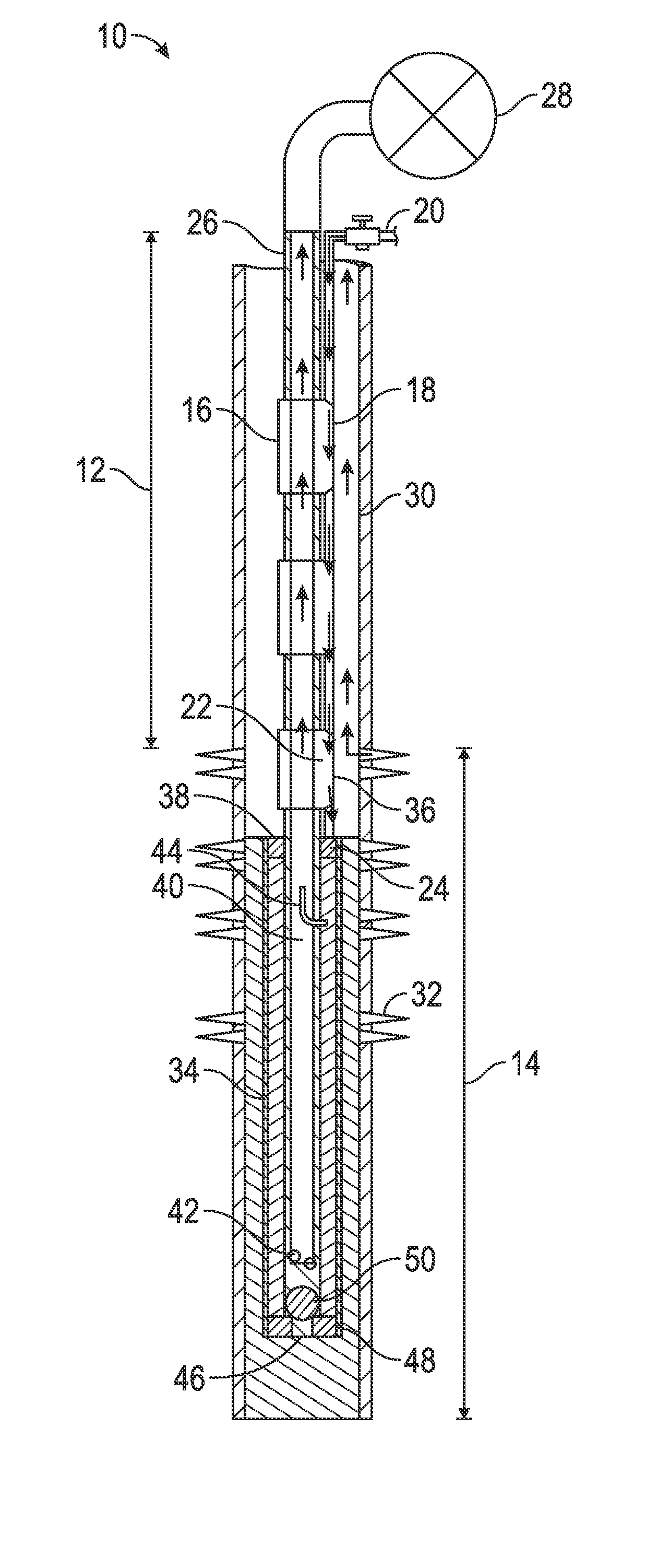
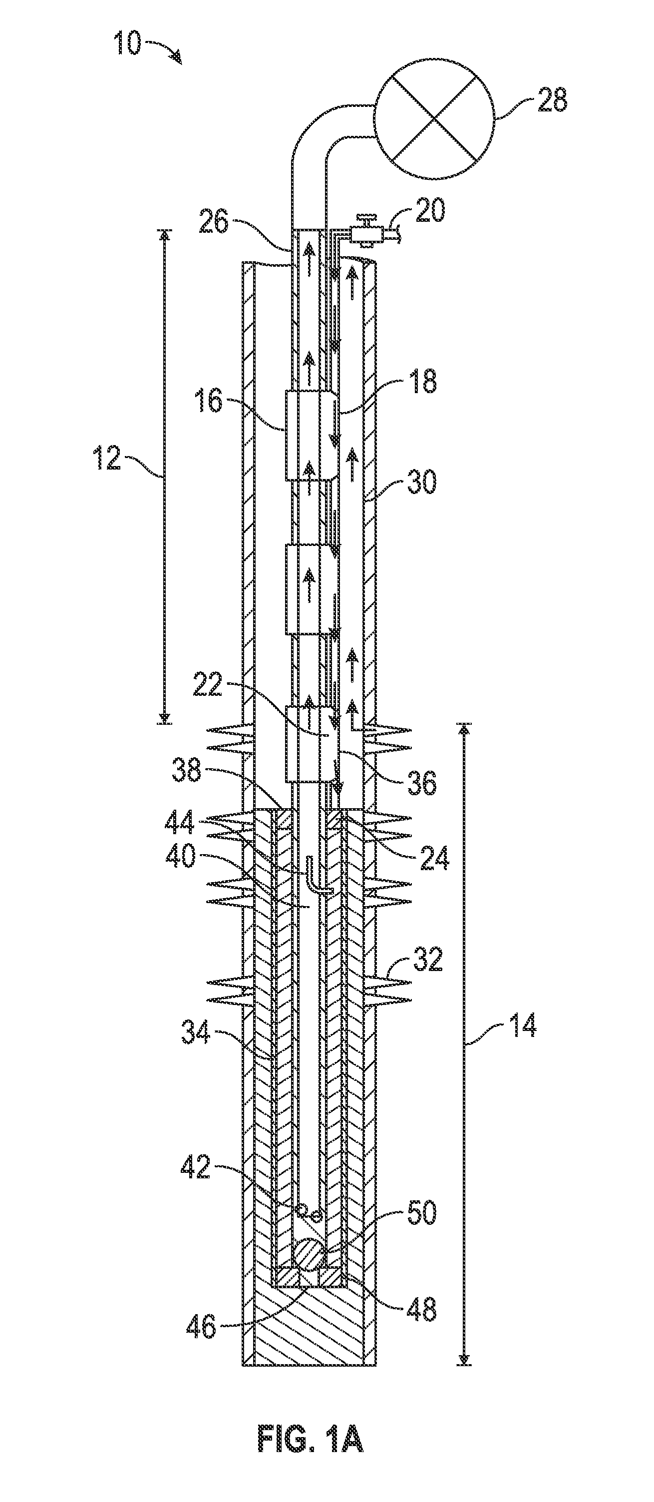
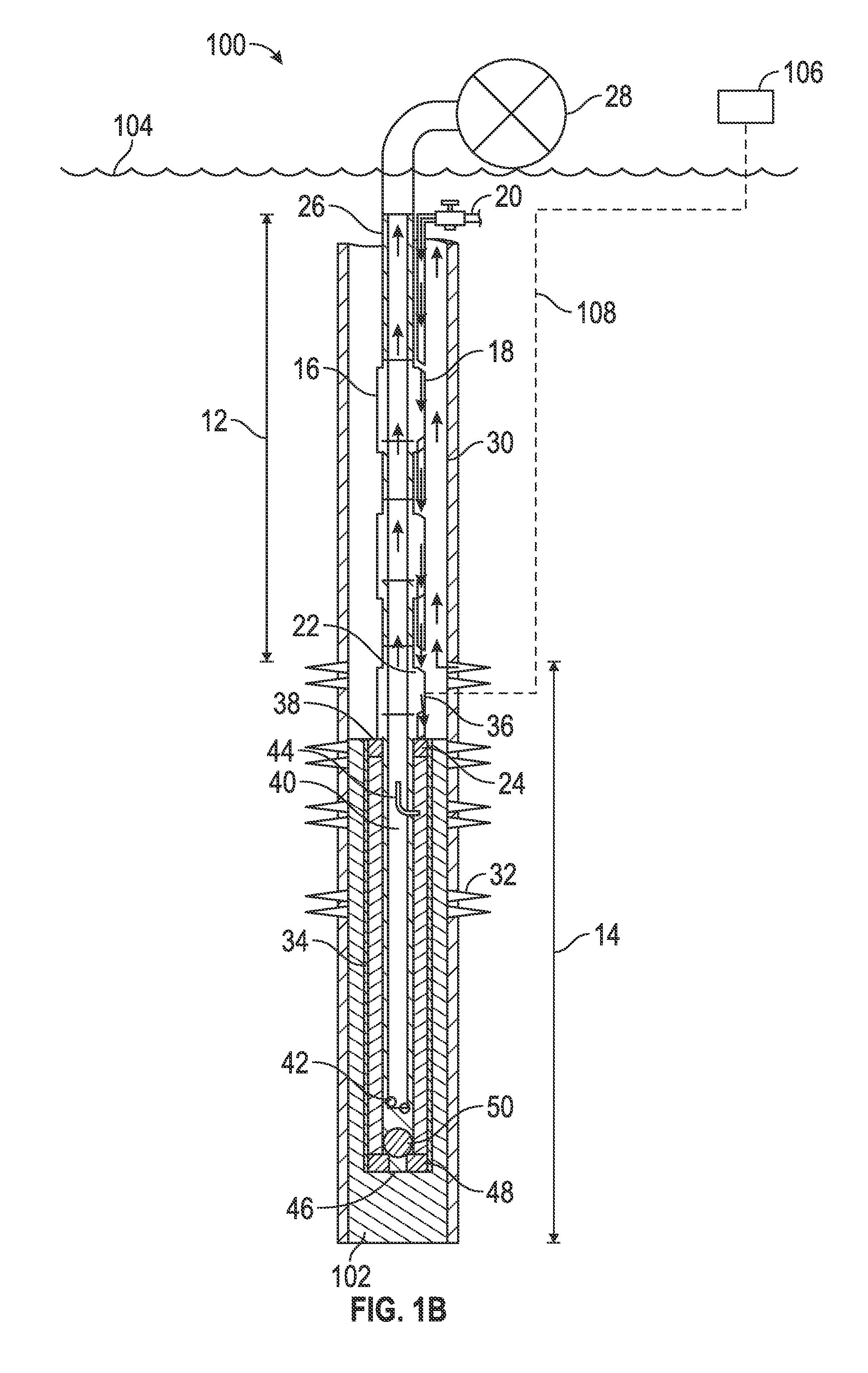
[0044]The Figures described above and the written description of specific structures and functions below are not presented to limit the scope of what Applicants have invented or the scope of the appended claims. Rather, the Figures and written description are provided to teach any person skilled in the art to make and use the invention for which patent protection is sought.

[0045]Those skilled in the art will appreciate that not all features of a commercial embodiment of the invention are described or shown for the sake of clarity and understanding. Persons of skill in this art will also appreciate that the development of an actual commercial embodiment incorporating aspects of the present invention will require numerous implementation-specific decisions to achieve the developer's ultimate goal for the commercial embodiment. Such implementation-specific decisions may include, and likely are not limited to, compliance with system-related, business-related, government-related, and othe...


PUM


Abstract

Applicants have created systems, methods, and apparatuses for increasing the production of fluid from a subterranean well. The system can include a controller and upper and lower portions. The upper portion can include an injection valve for regulating the amount of a first gas injected into an injection conduit. The lower portion can include a chamber valve for regulating the flow of a second gas through an upper tubing string and a vent valve for regulating the flow of the first gas and a standing valve. The collected fluid creates pressure in the lower portion causing the second gas to flow from the lower tubing string to the upper tubing string. The controller controls the injection valve and is coupled to a pressure gauge for measuring pressure in the lower portion. With the aid of this system, well operators can increase production of subterranean well formations, such as gas wells, without increasing backpressure on those formations.

Description

CROSS REFERENCE TO RELATED APPLICATIONS[0001]The present application claims the benefit of and priority to U.S. Provisional Patent Application Ser. No. 61 / 833,723, filed Jun. 11, 2013, and the contents of which are hereby incorporated by reference in its entirety.STATEMENT REGARDING FEDERALLY SPONSORED RESEARCH OR DEVELOPMENT[0002]Not applicable.REFERENCE TO APPENDIX[0003]Not applicable.BACKGROUND OF THE INVENTION[0004]1. Field of the Invention[0005]The inventions disclosed and taught herein relate generally to gas lift systems, apparatuses, and methods thereof. More specifically, the inventions described herein relate to increasing the production of gas wells through the use of an injection conduit fed bottle chamber of a gas well bore apparatus.[0006]2. Description of the Related Art[0007]The inventions disclosed and taught herein are directed to an improved system for increasing the production of a gas well. Although these inventions can be used in numerous applications, the inve...

Claims


Application Information

Patent Timeline
Patent Type & Authority Applications(United States)
IPC IPC(8): E21B43/12F04F1/20
CPCF04F1/20E21B43/122E21B43/123E21B2200/04
Inventor WILDMAN, SAMUELGLASOFER, JOSEPHMCCRADY, JOHNLOPEZ, RICARDO
Owner LUFKIN GEARS LLC
Why Eureka
Try Eureka