Electrode Module

a technology of electrodes and electrodes, applied in the field of electrode modules, can solve the problems of unintended distortion of membranes, inability to adjust the seal to varied local circumstances, and permanent damage to membranes, and achieve the effect of reducing the efficiency of the battery system and reducing the flow resistance around the electrodes

Active Publication Date: 2014-12-11
CARL FREUDENBERG KG
View PDF20 Cites 18 Cited by
  • Summary
  • Abstract
  • Description
  • Claims
  • Application Information

AI Technical Summary

Benefits of technology

[0034]This is all the more important in that the flow resistance around the electrode is markedly lower than through the fibrous electrode. An elec

Problems solved by technology

A problem with this is that the seal is compressed from both sides onto a relatively thin membrane, the thickness of which as a rule is less than 1 mm.
With seal offsets, that can occur through manufacturing tolerances with stack assembly, the result can be an unintended distortion of the membrane, through which the membrane can be permanently damaged.
In addition, it is not possible to adjust the seal to varied local circumstances.
Additionally, it is not possible to have seal profiles inward or seal applications inward.
Then a cell is no longer capable of functioning.
Too tight securing of the felt or non-woven material—due for example to exc

Method used


Image

  • Electrode Module
  • Electrode Module
  • Electrode Module

Examples


Embodiment Construction

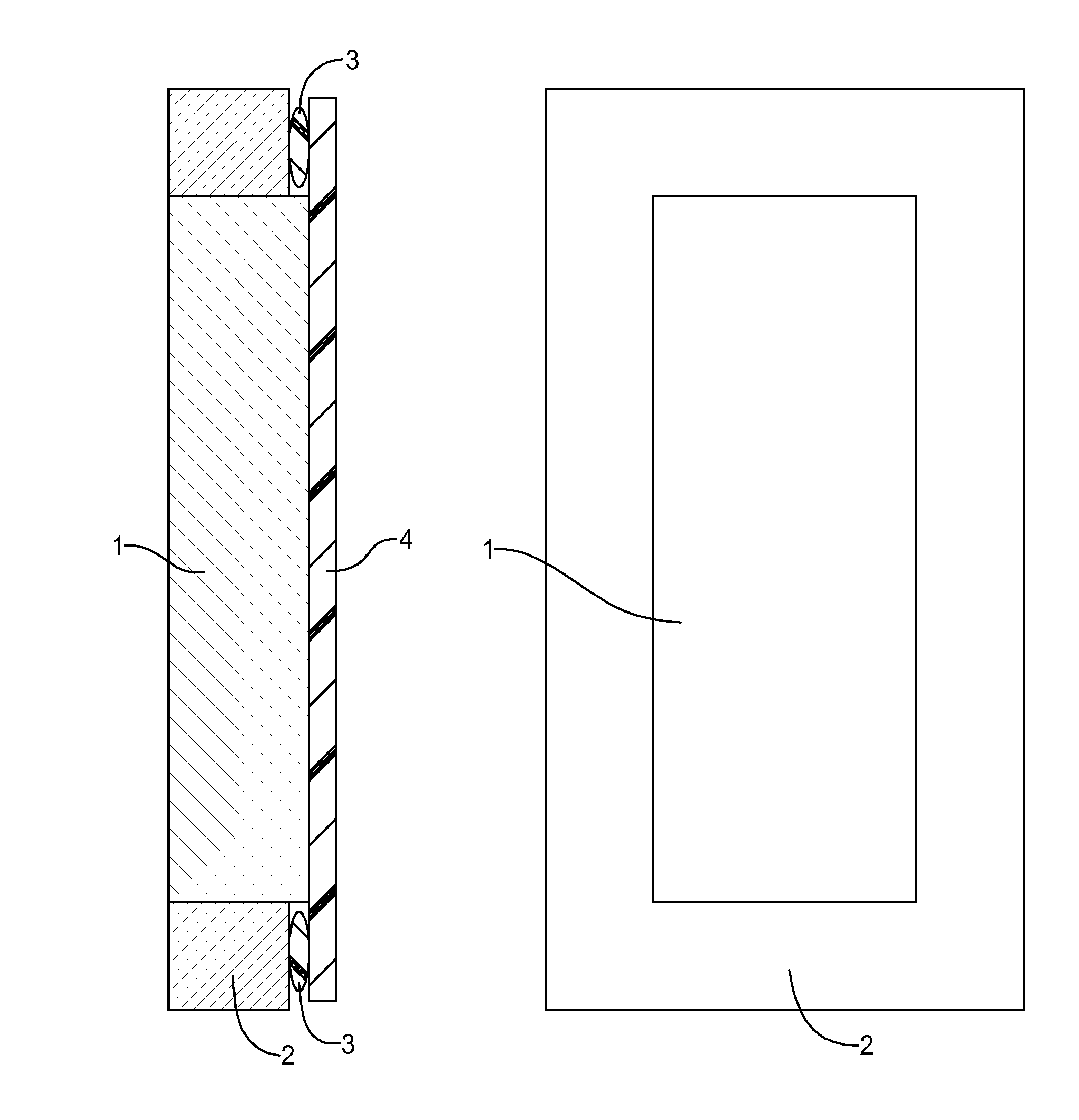
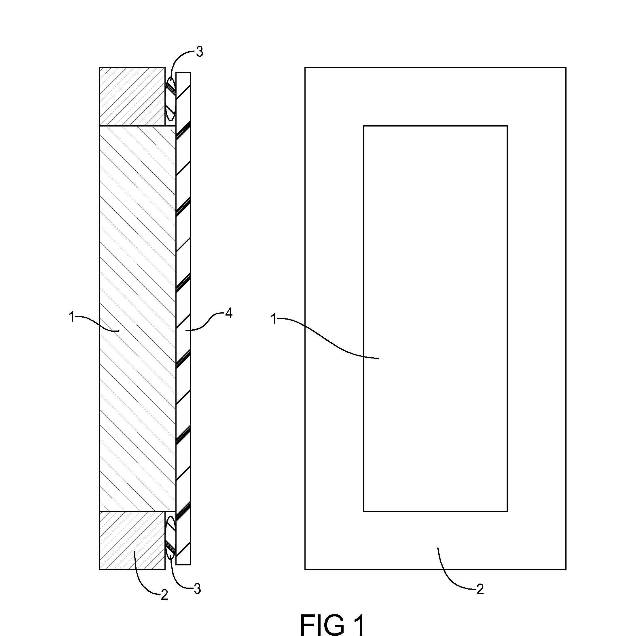
[0087]FIG. 1 shows in the left view a sectional view of an electrode module for a redox flow battery, comprising an electrode 1 and a sealing frame 2. The electrode 1 is mechanically connected with the sealing frame 2.

[0088]The right view of FIG. 1 shows a top-down view onto the electrode module.

[0089]The electrode 1 exhibits a nonwoven, which in sealing frame 2 exhibits a porosity that manifests 20% to 95%, preferably 50% to 95%, of its porosity in an uncompressed state.

[0090]In the left view as per FIG. 1 is shown that on sealing frame 2 a seal 3 is arranged. The seal 3 also adjoins a membrane 4.

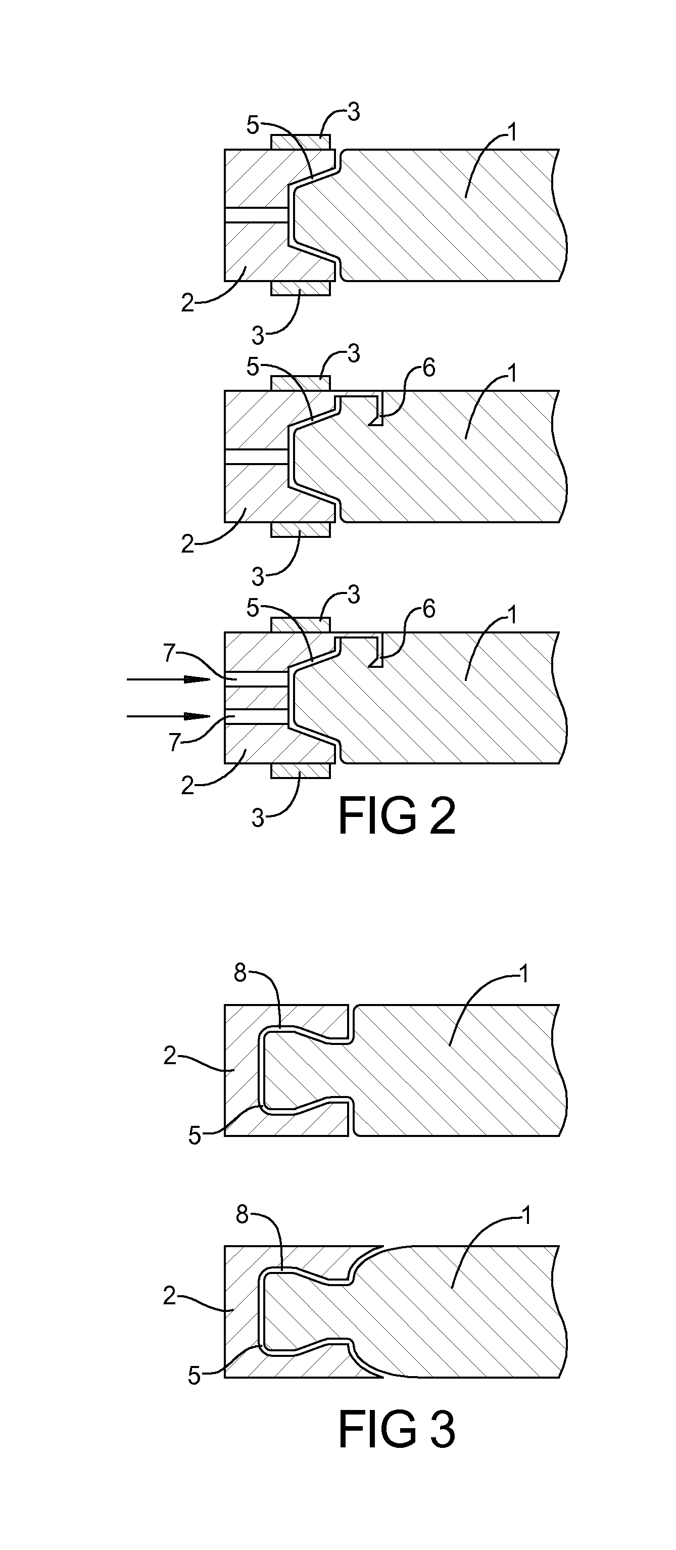
[0091]FIG. 2 shows in the upper view a sealing frame 2, on which a seal 3 is placed bilaterally. The sealing frame 2 exhibits a channel / groove 5. In this regard in the sealing frame 2 a surrounding channel 5 is configured. The channel 5 is configured to converge conically outward.

[0092]In the center view of FIG. 2, a sealing frame 2 is shown, which exhibits a clawing element 6. The clawing...


PUM

PropertyMeasurementUnit
Electrical resistanceaaaaaaaaaa

Abstract

An electrode module for a redox flow battery, includes an electrode (1) and a sealing frame (2), mechanically connected so that the electrode module that results therefrom can be used with no problems in redox flow cells.

Description

CROSS-REFERENCE TO RELATED APPLICATIONS[0001]This application claims the benefit and priority of German Patent Application No. 10 2013 009 629.4, filed Jun. 10, 2013. The entire disclosure of the above application is incorporated herein by reference.FIELD[0002]The present disclosure relates to an electrode module for a redox-flow battery.PRIOR ART[0003]Decentralized energy supplies require new concepts. With this as a background, redox flow batteries or redox flow cells are already known.[0004]A redox flow battery or redox flow cell, where “red-” stands for reduction, thus absorption of electrons, and “-ox” for oxidation, thus electron emission, is a storage battery.[0005]This battery or cell stores electrical energy in chemical compounds in that the reaction components are present in a solution in a dissolved or slurry form.[0006]Two energy-storing electrolytes circulate in two separate circuits, between which in the cell, by means of a membrane, ion exchange is occurring. The cell...

Claims


Application Information

Patent Timeline
IPC IPC(8): H01M8/02H01M8/20H01M8/18
CPCH01M8/0273H01M8/20H01M8/188H01M4/8605H01M8/0693H01M8/0276H01M8/0284H01M8/0297H01M8/04283Y02E60/50H01M8/24
Inventor KRITZER, PETERNAHRWOLD, OLAFJEANNE, OLIVIERZILS, SUSANNE
Owner CARL FREUDENBERG KG
Why Eureka
Try Eureka