Method of finishing a blade

a technology of finishing method and blade, which is applied in the direction of liquid fuel engine, program control, instruments, etc., can solve the problems of inability to accurately set the wall thickness of the finished blade, the effect of reducing the variation in the wall thickness between similar blades and reducing the weight of the componen

Active Publication Date: 2014-12-25
ROLLS ROYCE PLC
View PDF10 Cites 27 Cited by
  • Summary
  • Abstract
  • Description
  • Claims
  • Application Information

AI Technical Summary

Benefits of technology

[0013]By generating a bespoke tooling path for each component (such as a blade or vane) in the manner specified above and elsewhere herein, each component can be adaptively machined relative to the rest of the surface. This means that the finished component has a smooth surface with substantially no discontinuities, for example in rate of change of surface height or in curvature (which may be referred to herein as profile gradient). Thus, it could be said that the component's (aerodynamic) surface is adaptively machined to ensure that unwanted surface features may be removed in such a way that the resulting surface is blended (for example smoothly blended) back to the rest of the surface. This helps to optimize the aerodynamic performance of the component, which may be an aerofoil, or at least to ensure that it is as close to the design intent as possible.
[0045]According to an aspect, there is provided a method of finishing multiple aerofoils for use in a gas turbine engine, the method comprising performing the method as described above and elsewhere herein to each individual aerofoil. Accordingly, a bespoke tooling path that is unique to each aerofoil may be generated to remove the features identified for removal. In this way, the aerodynamic performance of each aerofoil may be optimized.

Problems solved by technology

Thus, many components need to be manufactured to very tight tolerances.
Even though the human operators are highly skilled, there is potential for the finished blades to contain inaccuracies, imperfections, or inconsistencies.
Such a blade may still be within inspection tolerance, but may contain minor imperfections on the surface that may have a significant detrimental impact on the performance of the blade.
Furthermore, the process is extremely labour intensive and time consuming, and thus expensive.
In addition, it is possible that the repetitive nature of the manual finishing of blades may lead to health problems for the operators.
This may avoid faceting on the machined surface of the component (such as an aerofoil), which may have a detrimental impact on aerodynamic performance.

Method used


Image

  • Method of finishing a blade
  • Method of finishing a blade
  • Method of finishing a blade

Examples


Embodiment Construction

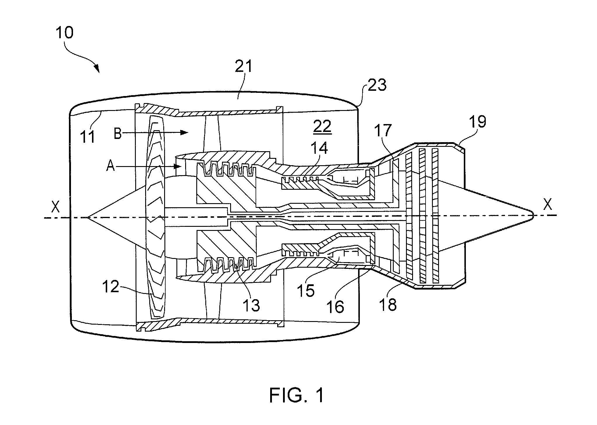
[0055]With reference to FIG. 1, a ducted fan gas turbine engine generally indicated at 10 has a principal and rotational axis X-X. The engine 10 comprises, in axial flow series, an air intake 11, a fan 12, an intermediate pressure compressor 13, a high-pressure compressor 14, combustion equipment 15, a high-pressure turbine 16, and intermediate pressure turbine 17, a low-pressure turbine 18 and a core engine exhaust nozzle 19. The engine also has a bypass duct 22 and a bypass exhaust nozzle 23.

[0056]The gas turbine engine 10 works in a conventional manner so that air entering the intake 11 is accelerated by the fan 12 to produce two air flows: a first air flow A into the intermediate pressure compressor 13 and a second air flow B which passes through the bypass duct 22 to provide propulsive thrust. The intermediate pressure compressor 13 compresses the air flow A directed into it before delivering that air to the high pressure compressor 14 where further compression takes place.

[005...


PUM

PropertyMeasurementUnit
surface heightaaaaaaaaaa
thicknessaaaaaaaaaa
thicknessaaaaaaaaaa

Abstract

An automated technique for finishing gas turbine engine blades or vanes by generating a bespoke tooling path for each blade or vane. The bespoke tooling path is generated by scanning the aerofoil surface to generate a 3-D electronic representation of the surface. The 3-D electronic surface is then analysed to identify imperfections or defects, and then a machining path a generated through which the imperfections can be removed. The machining path is determined so as to smoothly blend the surface back to the underlying surface where the imperfections had been present. In this way, the resulting aerofoil, once machined, has optimized aerodynamic performance.

Description

CROSS-REFERENCE TO RELATED APPLICATIONS[0001]This application is based upon and claims the benefit of priority from British Patent Application Number 1311053.1 filed 21 Jun. 2013 and British Patent Application Number 1311052.3 filed 21 Jun. 2013, the entire contents of which are incorporated by reference.BACKGROUND OF THE INVENTION[0002]1. Field of the Disclosure[0003]The present invention relates to a method of finishing a component. In particular, the present invention may be applied to the finishing of a blade for a gas turbine engine comprising adaptive machining of the blade's aerodynamic surface.[0004]2. Description of the Related Art[0005]Gas turbine engines comprise various precision engineered components. The precise dimensions of these components are crucial in determining the performance of the component, and thus the performance of the gas turbine engine, for example in terms of specific fuel consumption. Thus, many components need to be manufactured to very tight tolera...

Claims


Application Information

Patent Timeline
Patent Type & Authority Applications(United States)
IPC IPC(8): F01D5/14F01D9/02
CPCF01D5/147F05D2230/18F01D9/02G05B2219/45147G05B19/401G05B2219/37365G05B2219/37569G05B2219/37571G05B2219/50067G05B2219/50207Y10T29/49336
Inventor HANLON, ROISIN LOUISE
Owner ROLLS ROYCE PLC
Why Eureka
Try Eureka