Supercharge Your Innovation With Domain-Expert AI Agents!

Input current switching regulator system with low quiescent current

a regulator system and input current technology, applied in the direction of electric variable regulation, process and machine control, instruments, etc., can solve the problems of waste of power, excessive current drawn from the input source, and inability to supply the peak current needed during the periods of high load current, so as to maximize the utilization of the voltage source and maximize the battery life

Inactive Publication Date: 2014-12-25
SILICON LAB INC
View PDF8 Cites 16 Cited by
  • Summary
  • Abstract
  • Description
  • Claims
  • Application Information

AI Technical Summary

Benefits of technology

The patent text talks about a way to determine the highest level of input current through an inductor. This is important because it helps to maximize the use of the battery if it is the voltage source. The text explains that by selecting the right amount of inductance, the battery life can be extended.

Problems solved by technology

Small batteries, solar cells, and other “weak” power sources may be capable of supplying the average load to these systems, but may not be capable of supplying the peak current needed during the periods of high load currents.
A conventional switching regulator may be employed to extract power from the source and provide a useable, regulated voltage, but excessive current may be drawn from the input source during the periods of high load currents.
When excessive current is drawn from a battery, a voltage drop through the series impedance of the battery results in wasted power.
Repetitive periods of excessive current generally shortens battery life.
A typical switching regulator, however, attempts to recharge the capacitor at an uncontrolled rate, which is usually a high rate, again drawing excessive current from the source.
A current limit at the switching output of the regulator does not solve this problem, since the actual current drawn from the source varies as the source voltage varies and the output voltage changes with the charging output capacitor.
When not operating, however, the peripheral may still draw a small, yet finite unwanted leakage current that may adversely impact battery life.
This activation time was often significant, and variable, constraining the system to be configured to handle the latency and causing significant challenges for providing fast reacting peripherals.

Method used


Image

  • Input current switching regulator system with low quiescent current
  • Input current switching regulator system with low quiescent current
  • Input current switching regulator system with low quiescent current

Examples


Embodiment Construction

[0028]The benefits, features, and advantages of the present invention will become better understood with regard to the following description, and accompanying drawings. The following description is presented to enable one of ordinary skill in the art to make and use the present invention as provided within the context of a particular application and its requirements. Various modifications to the preferred embodiment will, however, be apparent to one skilled in the art, and the general principles defined herein may be applied to other embodiments. Therefore, the present invention is not intended to be limited to the particular embodiments shown and described herein, but is to be accorded the widest scope consistent with the principles and novel features herein disclosed.

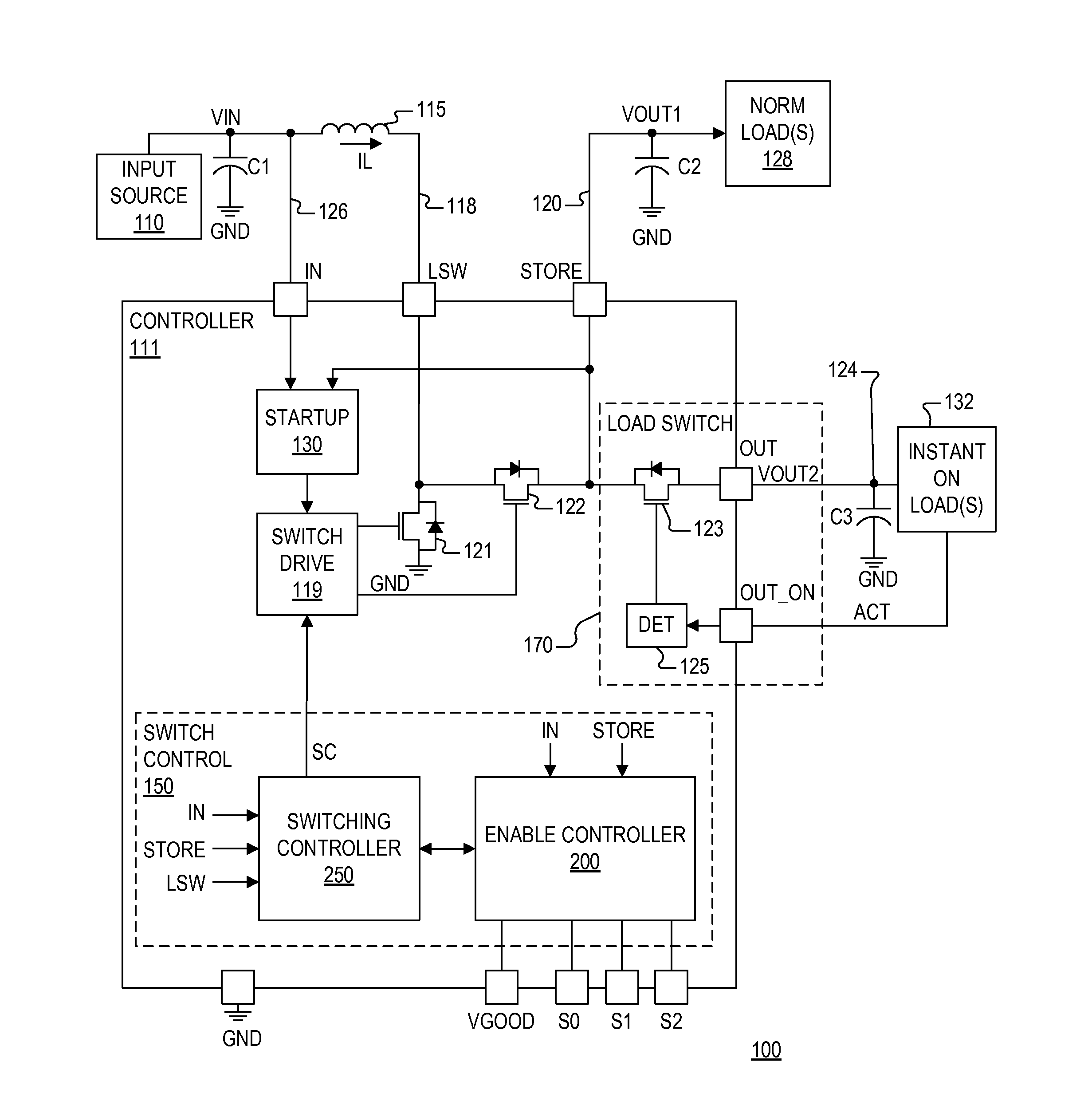
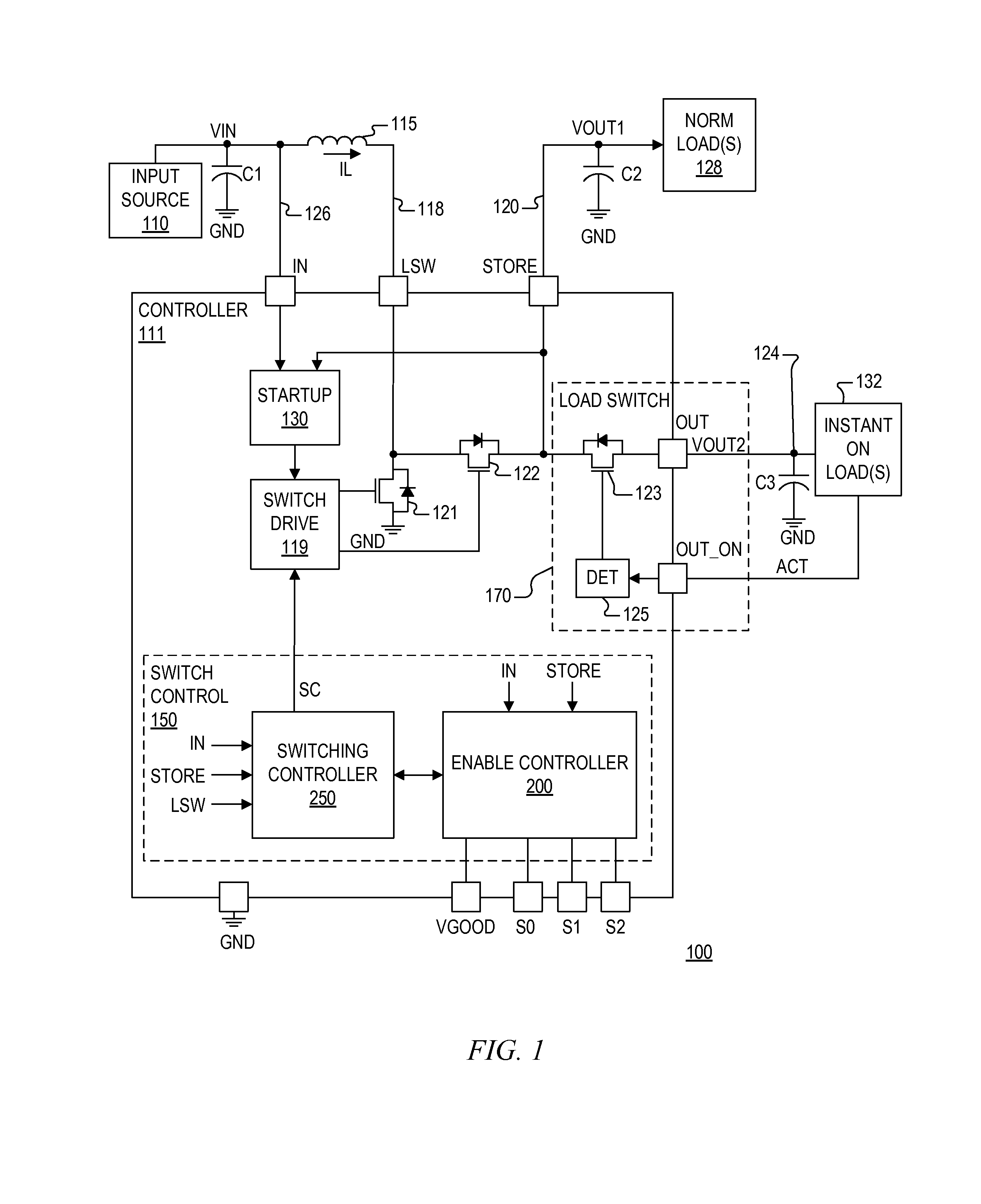
[0029]There is a need to efficiently extract power from a “weak” power source, such as a solar cell or a small battery or the like, without drawing excessive currents from the power source. There is also the need to s...


PUM


Abstract

A regulator controller including terminals for coupling to a voltage source, an inductor and an output capacitor, and including a switching circuit and a switch control circuit. The switching circuit includes switches that toggle coupling of the inductor during switching cycles based on charge and discharge periods. The switch control sets a duration of the charging period based on the input voltage and sets duration of the discharging period based on a difference between the input and output voltages. Multiple output terminals allow coupling to different load types, in which the output terminals may be temporarily coupled together to handle bursted loads. Thus, an output store capacitor may be coupled to handle a bursted load, and then decoupled for charging. Comparator circuits enable / inhibit switching based on input and output conditions. The regulator controller maximizes utilization of weak power sources while sufficiently handling typical load profiles.

Description

CROSS-REFERENCE TO RELATED APPLICATIONS[0001]This application claims the benefit of U.S. Provisional Application Ser. No. 61 / 837,492, filed on Jun. 20, 2013, which is hereby incorporated by reference in its entirety for all intents and purposes.BACKGROUND OF THE INVENTION[0002]1. Field of the Invention[0003]The present invention relates in general to switching regulator systems, and more particularly to a scalable input current switching regulator system with low quiescent current useful for weak power sources.[0004]2. Description of the Related Art[0005]The load profile of microcontroller-based systems is often characterized by long periods of very low load currents while the microcontroller is in a quiescent, idle state, punctuated by short periods of high load currents when the microcontroller wakes up and controls some activity, such as a brief radio transmission or other higher power operation. Small batteries, solar cells, and other “weak” power sources may be capable of suppl...

Claims


Application Information

Patent Timeline
Patent Type & Authority Applications(United States)
IPC IPC(8): H02M3/156H02M1/00
CPCH02M3/156H02J7/345H02M1/009H02M3/1588
Inventor TOMASZ, MARTINNGUYEN, TRANG MINH
Owner SILICON LAB INC
Features
  • R&D
  • Intellectual Property
  • Life Sciences
  • Materials
  • Tech Scout
  • Unparalleled Data Quality
  • Higher Quality Content
  • 60% Fewer Hallucinations
Learn More