Metal working power supply converter system and method

Active Publication Date: 2014-12-25
ILLINOIS TOOL WORKS INC
View PDF8 Cites 14 Cited by
  • Summary
  • Abstract
  • Description
  • Claims
  • Application Information

AI Technical Summary

Benefits of technology

The present patent discloses solutions for welding and cutting power supplies. The system includes a converter circuit with two solid state switching circuits each containing power electronic switches to produce output power at a controlled level. The circuits are electrically coupled in parallel to output a combined power. A control circuit is coupled to the solid state circuits and provides PWM control signals to maintain the desired loading of the circuits regardless of the output power level. The control circuit determines the duration of the control signals for each cycle and applies the signals to the first circuit without re-determining the duty cycle. This results in a more efficient and responsive control system. A method is also provided to apply the control signals to each circuit and determine the duration based on the desired duty cycle. The technical effects of this patent include improved control efficiency and responsiveness for welding and cutting power supplies.

Problems solved by technology

However, inductors in such systems can be quite large, implying additional cost and weight.
One problem in such systems exists insomuch as independently controlled inverter circuits can become unbalanced during operation.
The result can be a “walking” deviation in the duty cycles of the two inverters, in which one of the inverters will tend to progressively take on most of the load, causing thermal imbalance, undermining the benefits obtained by the use of multiple inverters.
Moreover, current systems may not account for the magnetic dynamics of transformer circuits in the power converters.

Method used


Image

  • Metal working power supply converter system and method
  • Metal working power supply converter system and method
  • Metal working power supply converter system and method

Examples


Embodiment Construction

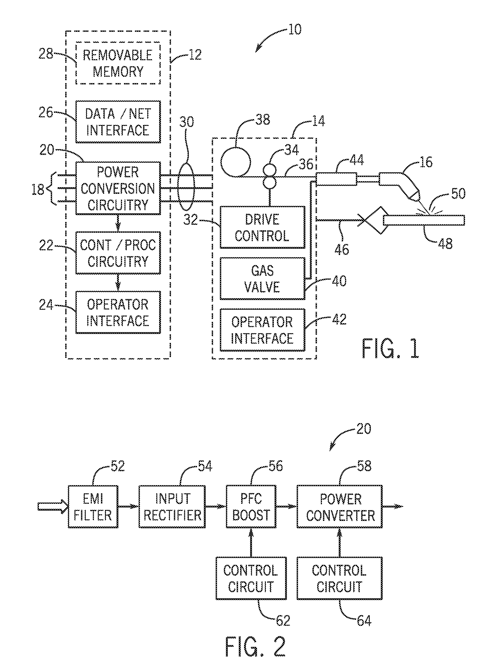
[0017]FIG. 1 illustrates an exemplary welding system 10 in the form of a GMAW system, and in particular a MIG welding system. In this exemplary system a power supply 12 receives and converts power that is applied to a wire feeder 14. The wire feeder delivers the power to a welding torch 16 for completing a welding operation. Although the present disclosure used this GMAW power supply as an exemplary basis for presentation of the new circuitry and control techniques, it should be understood that the same teachings may be applied to power supplies used for other welding processes, as well as for other metal working processes, such as plasma cutting.

[0018]The power supply 12 receives input power 18 from any suitable source, such as the power grid, an engine generator set, hybrid power supplies, fuel cells, batteries, or a combination of these. Power conversion circuitry 20 converts the power to a form suitable for a welding (or other metal working) process. The power supply may be desi...


PUM

PropertyMeasurementUnit
Fractionaaaaaaaaaa
Electrical inductanceaaaaaaaaaa

Abstract

A power supply for welding, cutting and similar operations includes a dual two-switch forward converter. The converter has two inverter circuits coupled in parallel but controlled to provide output power in an interleaved fashion. To avoid “walking” of the circuits (which could result in different duty cycles and imbalance of the load sharing), control signals are determined and applied to a first of the inverter circuits, and “on” times of the first circuit is monitored, such as by augmenting a counter to determine the number of clock cycles the first circuit is “on”. The same duration is then used for commanding output from the second inverter circuit. The duty cycles of both circuits is thus ensured to be the same regardless of changes in the total output power.

Description

BACKGROUND[0001]The invention relates generally to a field of welding systems and systems for performing metal working operations, such as gas metal arc welding (GMAW). More particular, the disclosure relates to innovations in the control of power supplies and converter circuitry used in such systems.[0002]Many applications exist for welding and cutting systems used to join two or more workpieces to one another, or to cut workpieces. These applications exist throughout industry, but also for construction, ship building, maintenance, and so forth. In arc welding systems, electrical power is converted to a form useful for a welding process, and the power provides voltage and current necessary to establish and maintain arcs between an electrode and a workpiece. Plasma cutting and similar operations also require conditioned power adapted for the specific process. In gas metal arc welding (GMAW), the arc is established between an electrode that is advanced towards the workpiece and of th...

Claims


Application Information

Patent Timeline
IPC IPC(8): H02M3/28
CPCH02M3/285B23K9/093B23K9/1043H02M1/08H02M3/1584H02M3/33523
Inventor MANTHE, ALAN A.DUNAHOO, JASON ALANKNOENER, CRAIG STEVENPOULOSE, MARY DIVYA
Owner ILLINOIS TOOL WORKS INC
Why Eureka
Try Eureka