Urine drainage device, drainage control device, drainage control system and voiding method

a technology of urinary drainage and control device, which is applied in the field of medical devices, can solve the problems of inability to protect the entire urinary tract system, the adhesion of the bladder wall, and the detrusor and internal bladder sphincter of the patient in a long disuse state, so as to achieve the restoration of communication between the urine storage cavity and the urine outl

Inactive Publication Date: 2014-12-25
BEIJING WANSHENG RENHE TECH
View PDF36 Cites 11 Cited by
  • Summary
  • Abstract
  • Description
  • Claims
  • Application Information

AI Technical Summary

Benefits of technology

[0011]The purpose of the present invention is to provide a urine drainage device comprising a urine inlet capable of connecting to the urinary catheter which is inserted into the human body and a urine outlet capable of connecting to the urine storage bag which stores urine, the urine drainge device further comprises a bionic bladder unit, the bionic bladder unit comprises a main body component capable of forming a urine storage cavity which strores urine, the urine storage cavity is connected to the urine inlet and the urine outlet via a connecting tube, the main body component comprises a first pressure transmission surface and a second pressure transmission surface capable of deforming with the change of the urine presure in the urine storage cavity, the connecting tube connecting the urine storage cavity and the urine outlet is a lower connecting tube, the lower connecting tube is provided with a first action area and a second action area on which external forces can be applied, the first action area and the second action area are oppositely disposed; when the external force is applied on both the first action area and the second action area simultaneously, the communication between the urine storage cavity and the urine outlet is blocked; the external force applied on the first action area and / or the second action area can be removed according to the deformation of the first pressure transmission surface and / or the second pressure transmission surface, and when any one external force applied on the first action area and the second action area is removed, the blockage between the urine storage cavity and the urine outlet can be removed, the communication between the urine storage cavity and the urine outlet can be restored. When the first pressure transmission surface and the second pressure transmission surface have the same function, the first pressure transmission surface or the second pressure transmission surface can be selected and used according to the actual need; similarly, when the first action area and the second action area have the same function and effect, the first action area or the second action area can be selected and used according to actual need. The urine storage cavity for storing urine is formed on the main body component, the urine storage cavity is communicated with the bladder in human body via a urinary catheter, and when the two are in different horizontal positions, the urine pressure in the bladder in human body and the urine pressure in the urine storage cavity can be mutually calculated according to the height difference, and therefore, collecting the changes of the urine pressure in the urine storage cavity can directly obtain the changes of urine pressure in the bladder in human body.

Problems solved by technology

The urinary catheter continuously outputs the urine in the bladder, which results in that no normal internal pressure of the bladder can be formed, so that the detrusor and internal bladder sphincter of the patient are in a long period of disuse state.
Consequently, the entire urinary tract system can not be protected by using the urinary continence principle of storing urine at low pressure and micturating at low pressure.
Long-term use of urinary catheters in such a structure will produce the following risks.
1. The continuous drainage by the urinary catheter makes the bladder of a patient lack filling state for a long time, easily leads to adhesions of bladder wall.
2. The continuous drainage by the urinary catheter decreases the pressure gradient between the bladder and the outside, so that, in order to ensure a smooth drainage, it is often required to increase the outer diameter, hardness, etc. of the catheter wall, which results in the oppression of the urethral mucosa of the patient and the occurrence of ischemic injury.
The purpose of the avove-mentioned setting of the preset time is to prevent automatically starting the micturition to void the bladder because of the pseudo transiently increased bladder pressure in the patient caused by postural changes, coughing, sneezing, bladder spasms and other factors, but the actual pressure has not reached the preset pressure, so that the purpose of simulating the physiological periodic micturition in human body cannot be achieved.
However, the above-mentioned devices have not made the correct handling for special conditions of the pseudo transiently increased bladder pressure in the patient.
Furthermore, the high pressure in the bladder can also make the urine escape into the gap between urinary catheter and the urethra, forming overflow of urine.
The urine between the urinary catherter and the urethra will become the culture medium for bacteria and viruses, and the bactera and viruses will also go backward into the bladder, leading to greater risks of infection.
In summary, for the risks of urinary reflux and overflow of urine caused by pseudo transiently increased bladder pressure as well as the contradiction between the pseudo transiently increased bladder pressure and the simulation of physiological micturition in human body, all the prior products have not disclosed any technical solutions to solve them.
The current products can no longer meet the requirements of a patient for a safe urinary catheterization.
This has brought great suffering to the patient, has increased the medical burden on the patient, and has increased the risks of infection.
Moreover, the existing urodynamic examinations cannot performing real-time monitoring on the urodynamic parameters, and cannot reflect the physiological state of the naturally filled bladder, and also cannot achieve individualized bionic urinary drainage, and they are especially inconvenient for those bedridden patients with indwelling urinary catheterization.
Currently, no such device has been reported which is capable of performing real-time urodynamic examination on patients underwent indwelling urinary catheterization.

Method used


Image

  • Urine drainage device, drainage control device, drainage control system and voiding method
  • Urine drainage device, drainage control device, drainage control system and voiding method
  • Urine drainage device, drainage control device, drainage control system and voiding method

Examples


Embodiment Construction

[0083]In order to make the purpose, the technical solution and the benificial effect of the present invention more clearly under understood, the specific embodiments of the present invention are further illustrated in detail below in conjuction with accompanied drawings. The illustrative embodiments and the description thereof of the present invention herein are used for explanation of the present invention, without limiting the present invention.

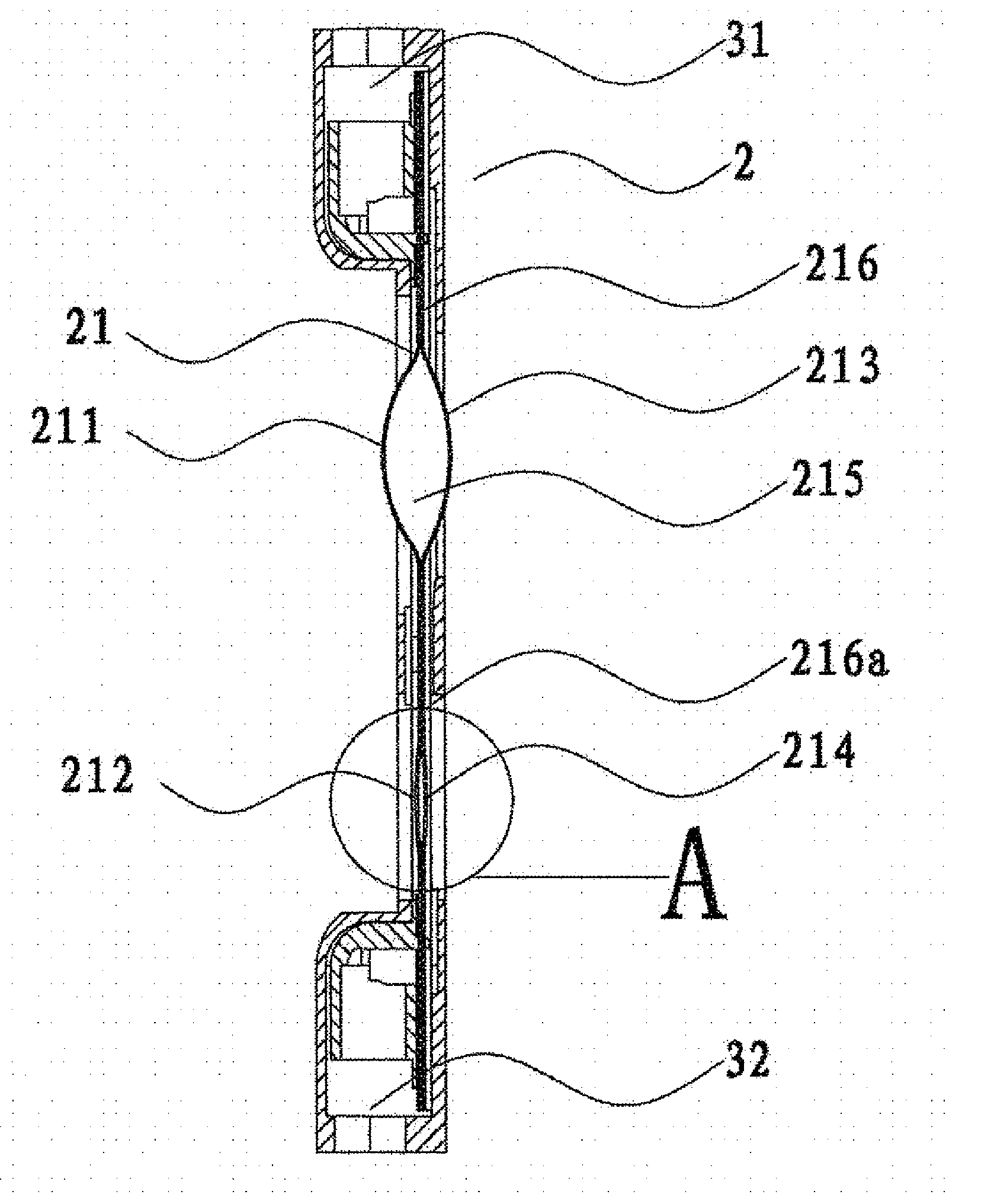
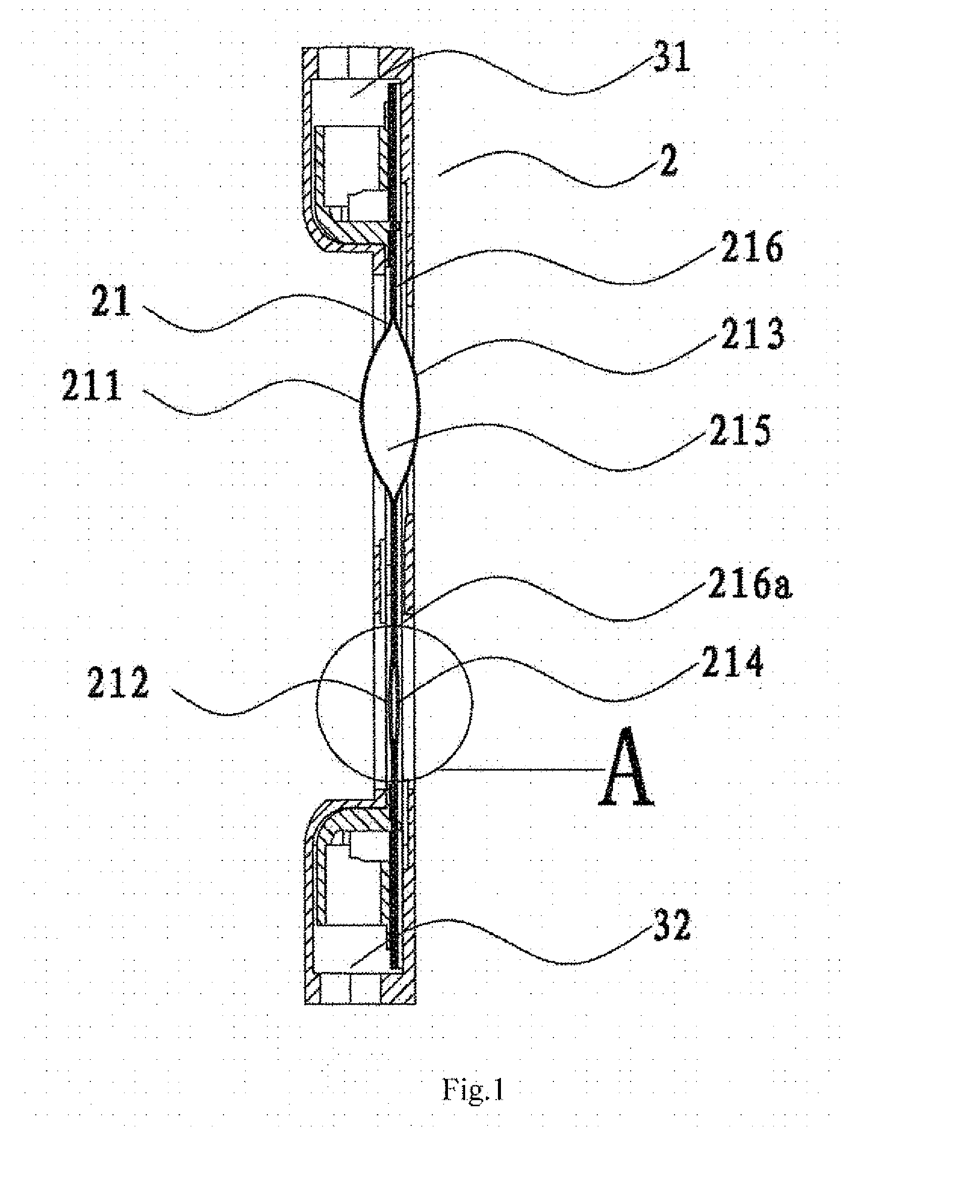
[0084]As is shown in FIG. 7, a urine drainage device comprises a urine inlet 31 capable of connecting to the urinary catheter which is inserted into the human body, and a urine outlet 32, the urine outlet 32 can connect to the urine storage bag 43 which stores urine, and can also connect to other components that can hold urine, i.e. the urine drainage device has the function capable of outputing the urine in the bladder of human body.

[0085]As is shown in FIG. 1, the urine drainage device further comprises a bionic bladder unit 2, the bionic...


PUM


Abstract

A urine drainage and control device and system, and voiding method includes a urine inlet, a urine outlet and a bionic bladder unit. The bionic bladder unit includes a urine storage cavity connected to the urine inlet and outlet via a tube, and a first and second pressure sensing surface deforming with urine pressure in the urine storage cavity. A lower connecting tube has a first and second action area. In one aspect when force is applied on the action areas simultaneously, communication between the urine storage cavity and the urine outlet is ended. Other applications of force allows communication with the urine outlet. The urine drainage device senses the change of the urine pressure via the deformation of the pressure sensing surfaces, determines whether to conduct voiding according to the deformation level of the pressure sensing surfaces thus assisting a patient to void.

Description

[0001]This application claims the priority of China Patent Application No. 201110457491.9, filed with the Patent Office of China on Dec. 31, 2011, titled “A URINE DRAINAGE AND CONTROL DEVICE THEREOF”, and the priority of China Patent Application No. 201120571031.4, filed with the Patent Office of China on the same day, titled “A URINE DRAINAGE AND CONTROL DEVICE THEREOF”, the contents of which are incorporated herein by reference in their entirety.FIELD OF THE INVENTION[0002]The present invention relates to the technical field of medical device, particularly to a urine drainage device, drainage control device, drainage control system and micturition method.BACKGROUND OF THE INVENTION[0003]Clinically, there are many patients of paraplegia and hemiplegia caused by cerebrovascular diseases and spinal vascular diseases, and patients with bladder fistula, coma patients, patients with high paraplegia, etc. Most of them are accompanied by disorders of micturition, and indwelling catheteriz...

Claims


Application Information

Patent Timeline
Patent Type & Authority Applications(United States)
IPC IPC(8): A61M1/00A61M25/00
CPCA61M1/008A61M25/0017A61M2205/07A61M2202/0496A61M1/0019A61F5/451A61B5/207A61M1/70A61M1/69A61M1/74A61M1/84
Inventor DONG, DONGSHENG
Owner BEIJING WANSHENG RENHE TECH
Why Eureka
Try Eureka