Hall effect thruster

a technology of hall effect and thruster, which is applied in the direction of machines/engines, cosmonautic vehicles, transportation and packaging, etc., can solve the problems of increasing the overall cost and complexity of space vehicles, affecting the reliability of space vehicles, and so as to achieve the effect of not affecting the stability of plasma jets

Active Publication Date: 2015-01-01
SN DETUDE & DE CONSTR DE MOTEURS DAVIATION S N E C M A
View PDF1 Cites 7 Cited by
  • Summary
  • Abstract
  • Description
  • Claims
  • Application Information

AI Technical Summary

Benefits of technology

[0017]The present invention also provides a space vehicle incorporating at least one such Hall effect thruster, and it also provides a method of regulating thrust in such a Hall effect thruster.
[0018]In at least one implementation of the thruster regulation method, the flow of propulsion gas injected into the annular channel by the circuit and / or an electric voltage between said anode and cathode change as a function of a desired thrust, and the position of the movable wall is regulated so as to adapt the cross-section of the downstream end of the annular channel as a function of said variable flow and / or of said variable voltage in such as a manner as to maintain the plasma density at the downstream end of the annular channel in a predetermined range. It is thus possible to vary the operation of the Hall effect thruster between a high thrust mode and a high specific impulse mode without affecting the stability of the plasma jet.

Problems solved by technology

Nevertheless, a Hall effect thruster with high specific impulse can normally only achieve thrust that is very low.
That nevertheless presents the drawback of increasing the overall cost and complexity of the space vehicle, to the detriment of its reliability.
Nevertheless, that document does not mention how to operate the Hall effect thruster both in high thrust mode and in high specific impulse mode.

Method used


Image

  • Hall effect thruster
  • Hall effect thruster
  • Hall effect thruster

Examples


Embodiment Construction

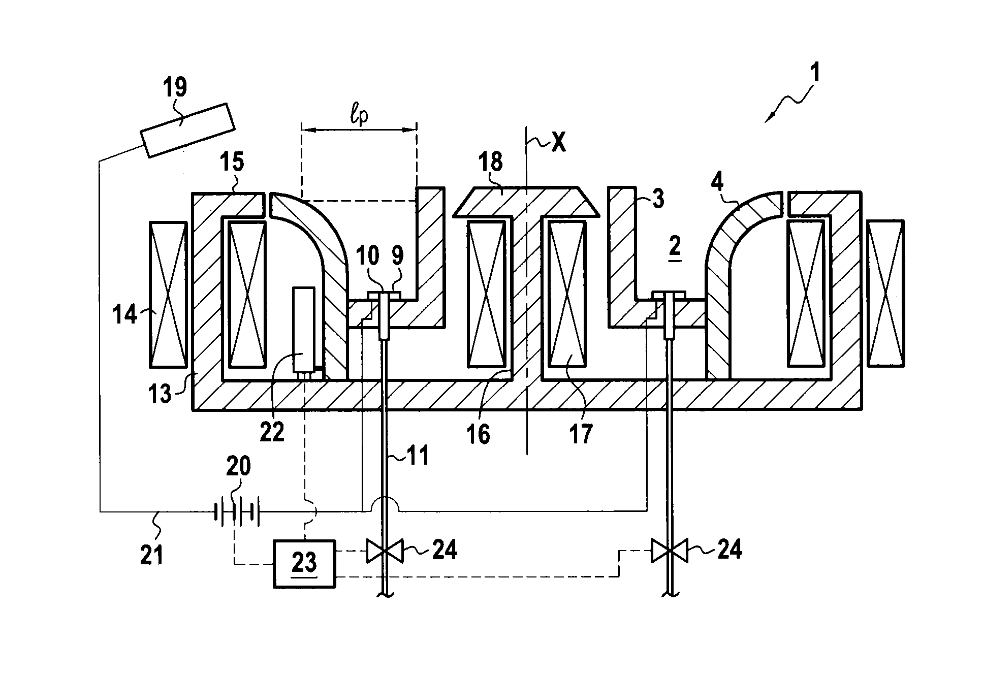
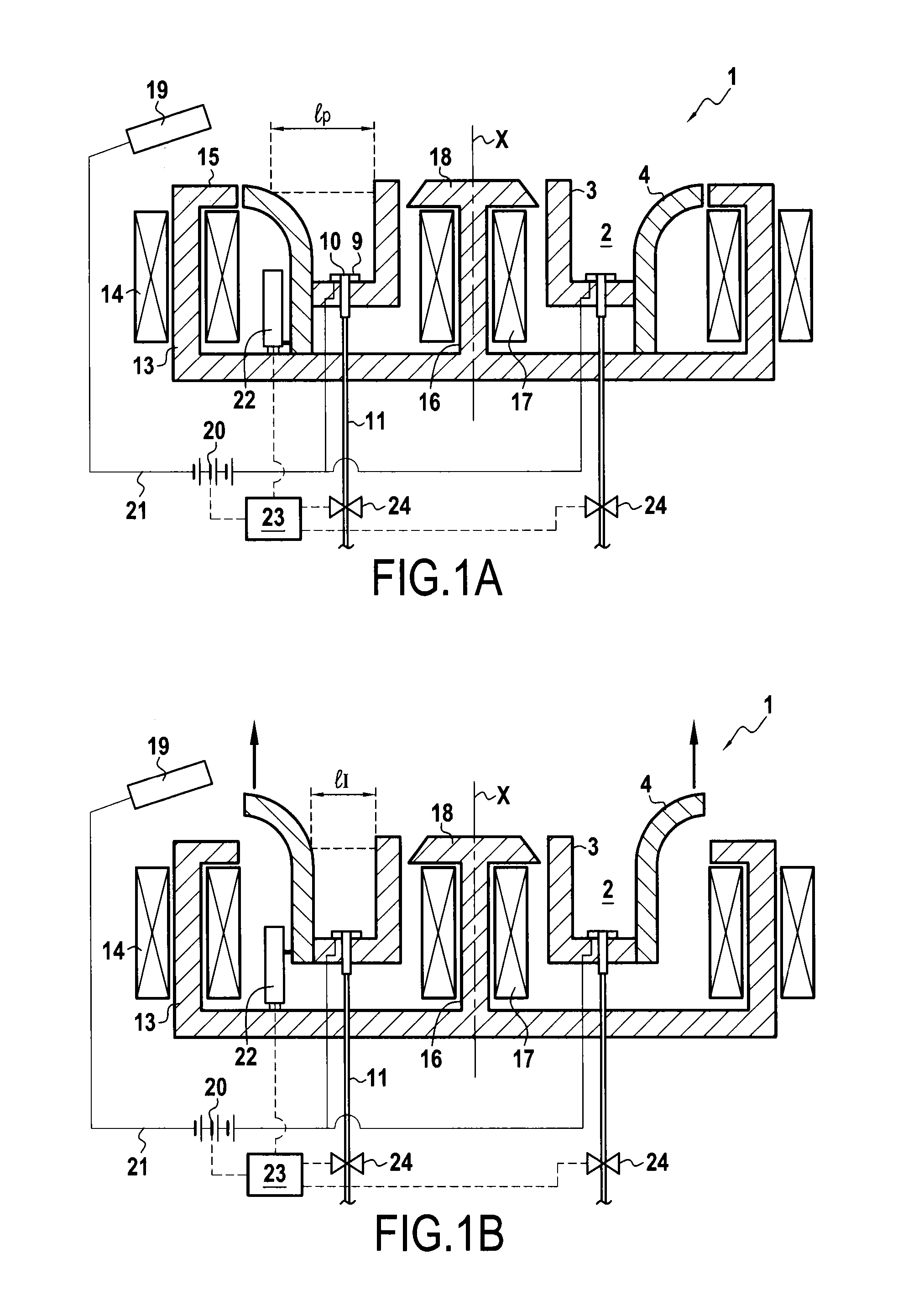
[0024]FIGS. 1A and 1B show two different positions of the same Hall effect thruster 1 in a first embodiment. This thruster 1 has an annular channel 2 defined by an inner wall 3 and an outer wall 4 made of ceramic material, which walls are coaxial about a central axis X. The annular channel 2 presents a downstream end that is open and an upstream end that is closed. At its upstream end, the annular channel 2 also presents nozzles 10 for injecting propulsion gas into the annular channel 2. The nozzles 10 are connected to a propulsion gas source by an injection circuit 11 including flow rate regulator devices 24. By way of example, these devices 24 may comprise a pencil valve or a thermo-capillary, i.e. a capillary with heater means making it possible actively to vary its temperature and thus the flow rate that it passes. Such flow rate regulator devices may also be associated with passive flow restrictors. The propulsion gas may be xenon, which presents the advantages of high molecula...


PUM


Abstract

A Hall effect thruster including a downstream end of its annular channel presenting a cross-section that is variable to vary a thrust and a specific impulse of the thruster.

Description

BACKGROUND OF THE INVENTION[0001]The present invention relates to the field of Hall effect thrusters.[0002]The invention relates more particularly to a Hall effect thruster having an annular channel, an anode, an injection circuit, a magnetic circuit, and a cathode. The annular channel is defined by an outer wall and an inner wall that are coaxial around a central axis, and it presents a downstream end that is open and an upstream end that is closed. The anode is situated at the upstream end of the annular channel. The injection circuit is suitable for injecting a propulsion gas, e.g. xenon, into the annular channel. The magnetic circuit is suitable for generating a magnetic field at the downstream end of the annular channel. The cathode is situated at the outside of the downstream end of the annular channel.[0003]In the present context, the terms “upstream” and “downstream” are defined relative to the normal flow direction of the propulsion gas in the direction defined by the centr...

Claims


Application Information

Patent Timeline
Patent Type & Authority Applications(United States)
IPC IPC(8): F03H1/00
CPCF03H1/0006F03H1/0075F03H1/00F03H1/0037B64G1/405F03H1/0068F03H1/0062
Inventor VIAL, VANESSA MARJORIEMOYON, JOEL
Owner SN DETUDE & DE CONSTR DE MOTEURS DAVIATION S N E C M A
Why Eureka
Try Eureka