

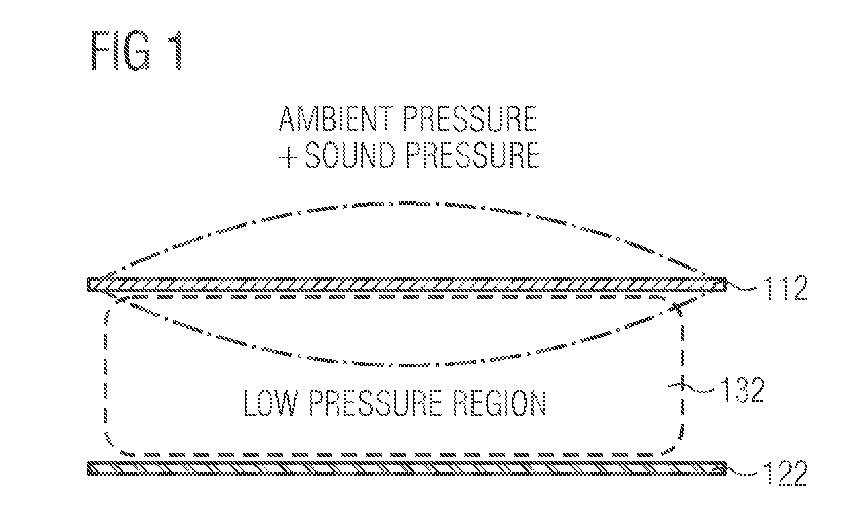
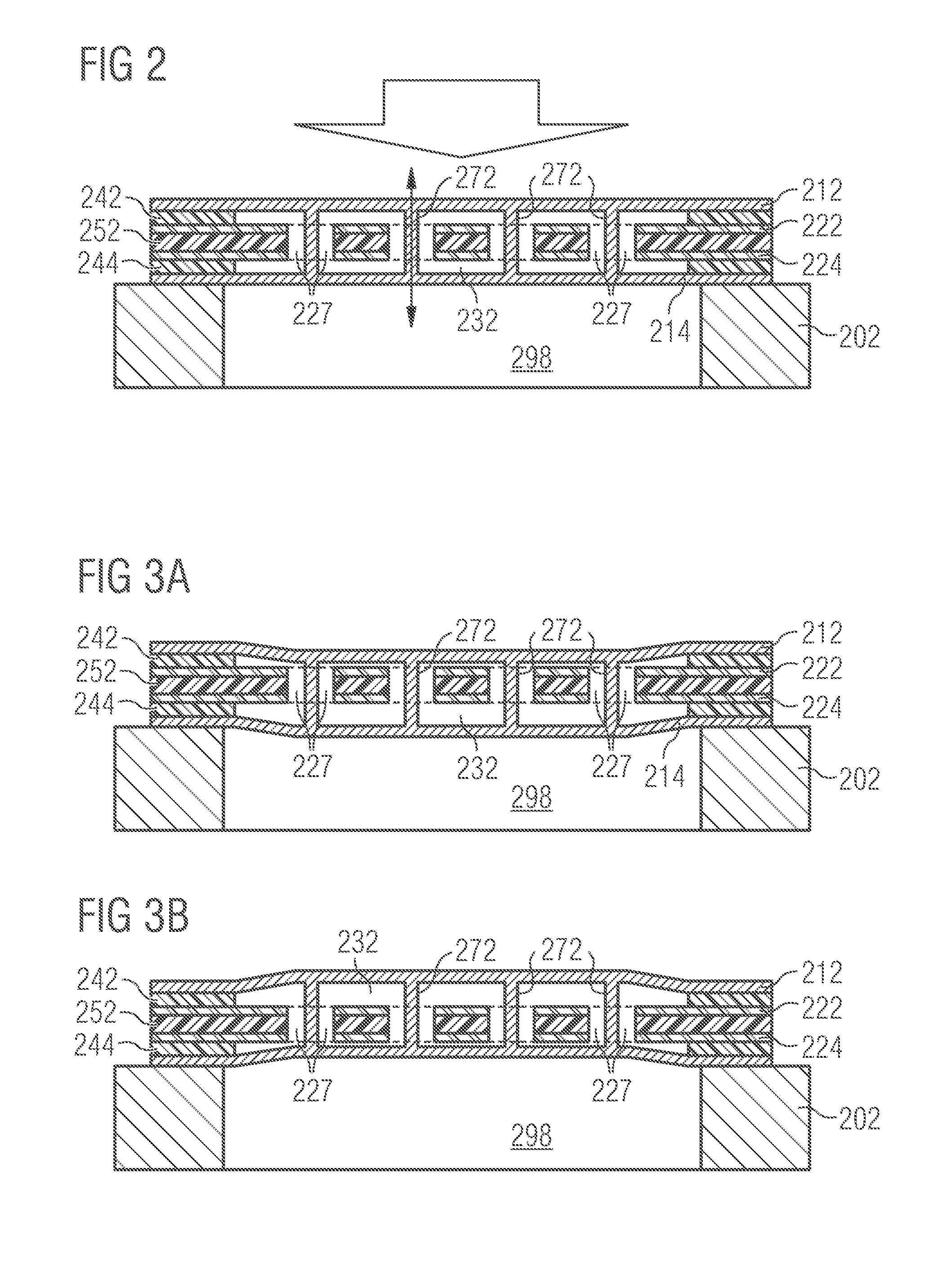
MEMS Microphone with Low Pressure Region Between Diaphragm and Counter Electrode
a micro-electromechanical system and microphone technology, applied in the direction of diaphragm construction, loudspeaker, electrostatic transducer, etc., can solve the problem of fluidic noise in between the fluidic noise of the interdigitated comb fingers may be limited by the construction of the condenser microphone, and the miniaturization of the transducer may pose new challenges in the desired high signal-to-noise ratio,
- Summary
- Abstract
- Description
- Claims
- Application Information
AI Technical Summary
Benefits of technology
Problems solved by technology
Method used
Image

Examples
Embodiment Construction
[0031]In the following description, a plurality of details are set forth to provide a more thorough explanation of embodiments of the present invention. However, it will be apparent to those skilled in the art that embodiments of the present invention may be practiced without these specific details. In other instances, well-known structures and devices are shown in block diagram form rather than in detail in order to avoid obscuring embodiments of the present invention. In addition, features of the different embodiments described hereinafter may be combined with each other, unless specifically noted otherwise.
[0032]Standard condenser microphones may use a parallel plate capacitance with change of gap distance by a membrane displacement. This may imply noise of air moving through the perforations. When studying the issue of SNR in today's microphones, the perforated backplate may be identified as one of the major noise contributors. One possible solution could be to remove the perfor...
PUM
| Property | Measurement | Unit |
|---|---|---|
| volume | aaaaa | aaaaa |
| volume | aaaaa | aaaaa |
| pressure | aaaaa | aaaaa |
Abstract
Description
Claims
Application Information