High Efficiency Continuous Micro Algae Bioreactor

a bioreactor and micro algae technology, applied in bioreactors/fermenters, biomass after-treatment, special use, etc., can solve the problems of high cost of methods, large land area, and inability to meet the needs of microorganisms, so as to increase the flow of flue gas and micronutrients, and reduce the spacing

Inactive Publication Date: 2015-01-01
CARL DAVID WAYNE
View PDF1 Cites 1 Cited by
  • Summary
  • Abstract
  • Description
  • Claims
  • Application Information

AI Technical Summary

Benefits of technology

[0009]The bioreactor is a large deep pond divided into separate channels. There are strands of lighting installed in each of the channels. Water and algae are added at point 2. Flue gas and other nutrients are added to the reactor at points (5) in each channel (6). As the water and algal medium progress through the pond the algae concentration increases. Therefore as the reaction progresses, more lighting and nutrients are required. This is accomplished by decreasing the spacing between the light strands and increasing the flow of flue gas and micronutrients.

Problems solved by technology

This method is costly and it has not been proven that the CO2 will remain sequestered.
The use of shallow open ponds has these primary drawbacks.
First, they require very large tracts of land for a typical fossil fuel burning electrical generating plant.
Very few electrical generating plants have that amount of available land near them.
Second, due to the large tract of land required, evening distribution of the flue gas and other nutrients throughout the pond such as to allow for efficient growth of algae is very difficult.
Without proper distribution of nutrients the pond will grow in an inefficient manner requiring more acreage to accomplish the same goal.
While it does grow in temperatures outside this range the growth rate is adversely affected.
In all but a few areas in the U.S., production would be severely limited in the winter and problematic during parts of the summer.
Fourth, the ponds are only illuminated with natural light.
This means they are only providing photosynthesis during days of sunlight.
Therefore, during nighttime and overcast days there usefulness is limited.
First is that they are very capital intensive.
Neither of these provides a low cost option for manufacturing the reaction vessel.
Because of these waste products the concentration of algae in the medium is limited.
Low algal concentration increases the cost of ‘harvesting’ the algae.
Since some micro nutrients may be toxic to the algal solution in high concentrations and you are limited as to how much dissolved carbon dioxide can be in the solution, the entire process is limited.

Method used


Image

  • High Efficiency Continuous Micro Algae Bioreactor
  • High Efficiency Continuous Micro Algae Bioreactor

Examples


Embodiment Construction

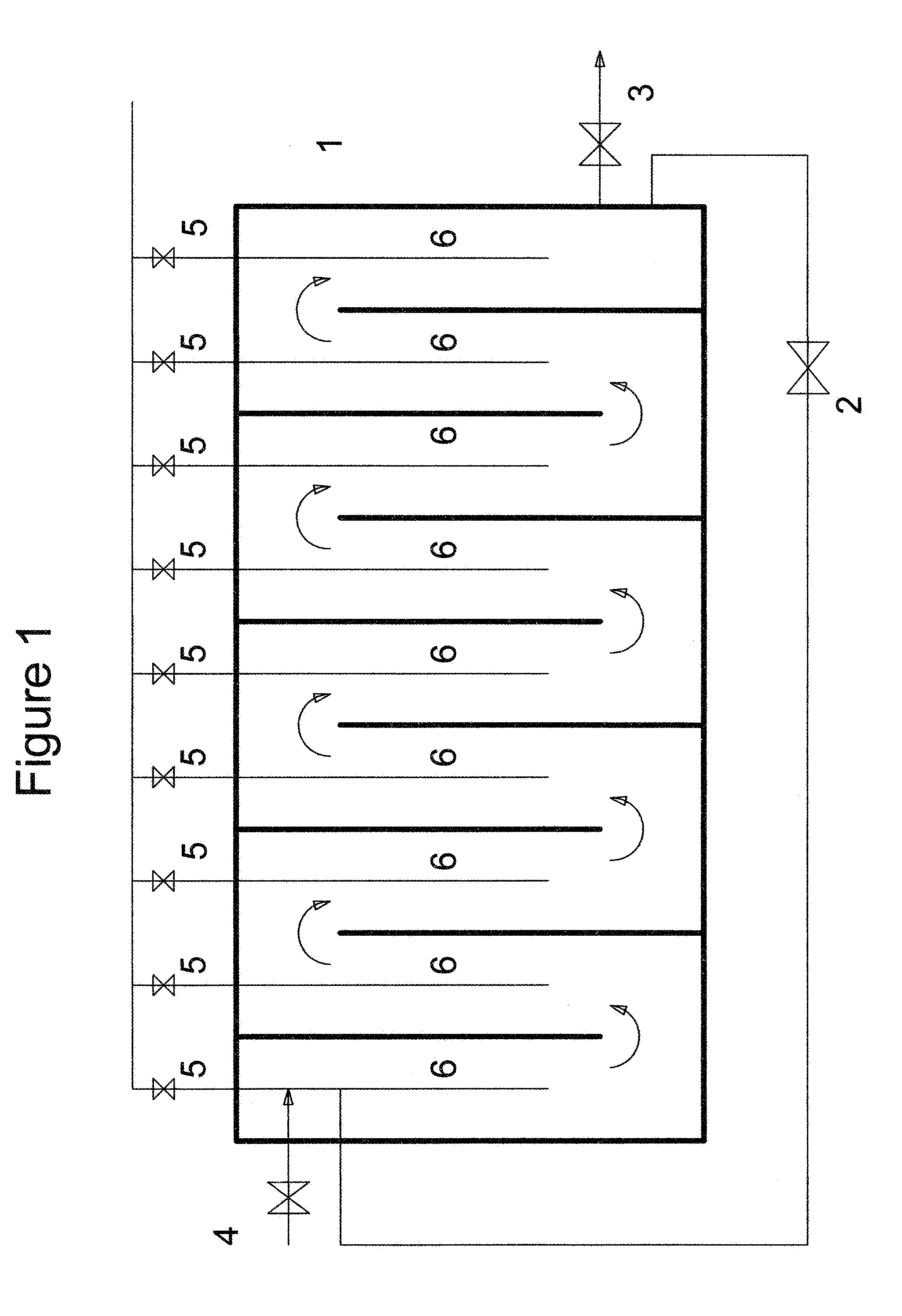
[0010]The bioreactor shall be a concrete pond the exact dimensions of which are dependent on the amount of flue gas available. The depth of the pond must be a minimum distance of 5 feet to provide for sufficient time to absorb the CO2 and other flue gases into the water. To conserve space a depth of at least 10 feet is most practical. The main factors determining the length and width of the bioreactor are the amount of flue gas to be consumed and the algal species chosen. Many algal species have shown the ability to more than double their mass in a 24 hour period. A 500 Mega Watt electrical generating facility would require a bioreactor as small as a square 400 feet on each side.

[0011]As shown on FIG. 1, water and algae are recirculated to the bioreactor via line (2). Nine channels are shown in FIG. 1, but the exact number would be determined by the magnitude of the source of carbon dioxide. A reactor 400 feet long would have as many as 40 channels. Nutrients are added at (5) along ...


PUM

PropertyMeasurementUnit
temperaturesaaaaaaaaaa
distanceaaaaaaaaaa
depthaaaaaaaaaa

Abstract

This process is unique in that it provides a continuous photosynthetic bioreactor for carbon sequestration. An on-site bioreactor directly decreases the concentration of carbon dioxide in the emissions of fossil fuel consuming units. In this process, an algal medium is maintained in a bioreactor. Light is provided through artificial means. Nutrients are added in a cross flow pattern and waste products are removed as they are created, allowing for maximum growth of the algae.

Description

BACKGROUND OF THE INVENTION[0001]1. Field of the Invention[0002]This invention generally relates to a continuous biological gas cleaning system for removing carbon dioxide from the gas stream of fossil fuel burning devices.[0003]2. Description of the Related Art[0004]The U.S. produces nearly 2 billion tons of CO2 annually from the combustion of fossil fuels. CO2 has been theorized to be a major contributor to the greenhouse gas effect and is therefore the primary culprit in global warming. As fossil fuel consumption continues it is theorized that CO2 concentrations in the atmosphere could double in the near future.[0005]For that reason many have investigated ways to capture and sequester CO2 emissions. Much work is being done in the area of solvent extraction of the CO2 and pumping it into salt mines or the ocean. This method is costly and it has not been proven that the CO2 will remain sequestered.[0006]Another option involves sequestering the CO2 with biological reactors. Currentl...

Claims


Application Information

Patent Timeline
Patent Type & Authority Applications(United States)
IPC IPC(8): B01D53/62B01D53/84
CPCB01D53/84B01D53/62B01D2251/95B01D2257/504Y02A50/20Y02C20/40
Inventor CARL, DAVID, WAYNE
Owner CARL DAVID WAYNE
Why Eureka
Try Eureka