Biopotential Signal Acquisition System and Method

a biopotential signal and acquisition system technology, applied in the field of acquisition of biopotential signals, can solve problems such as common mode interference, particular problems of common mode signals, and gain mismatch between active electrodes, and achieve the effect of large bandwidth amplifiers

Active Publication Date: 2015-01-01
INTERUNIVERSITAIR MICRO ELECTRONICS CENT (IMEC VZW) +1
View PDF6 Cites 26 Cited by
  • Summary
  • Abstract
  • Description
  • Claims
  • Application Information

AI Technical Summary

Benefits of technology

[0016]According to an embodiment, the test frequency is greater than 100 Hz and is not a multiple of 50 Hz or 60 Hz. In this way, the frequency of the test signal is above the biopotential signal bandwidth (for example 0.5 Hz-100 Hz), such that the test signal can be clearly differentiated from the biopotential signal and CMRR calibration can be performed during acquisition of the biopotential signal. Harmonics of the mains interference signals may also be avoided.
[0017]According to an embodiment, the test frequency is below 10 kHz. This avoids the need for very large bandwidth amplifiers.

Problems solved by technology

Thus, there may be a gain mismatch between the active electrodes.
Common mode interference is one of the problems in such active electrode biopotential signal acquisition systems.
The mains frequency generally falls within the frequency range of interest of biomedical signals, which makes such common mode signals a particular problem.
One potential problem is that the common mode interference at the inputs of the active electrodes can be converted to a differential mode error at the outputs of active electrode pairs due to the voltage gain mismatch between the active electrode pairs, as well as the contact-impedance mismatch.
The output error can have significant amplitude when compared to the amplitude of the biopotential signals.
The CMRR of active electrode systems is usually limited by this voltage gain mismatch (VCM *ΔA) between the signal active electrode and the reference active electrode, which in return is due to the process variation and component mismatch.

Method used


Image

  • Biopotential Signal Acquisition System and Method
  • Biopotential Signal Acquisition System and Method
  • Biopotential Signal Acquisition System and Method

Examples


Embodiment Construction

[0036]According to an embodiment, the disclosure provides an active electrode biopotential acquisition system in which the active electrodes provide digitized outputs. In the digital domain, a gain control signal is derived based on the response to a common mode test signal at a test frequency. This is fed back to one of the active electrodes and is used to adjust a gain of the active electrode. This provides a CMRR calibration system and method that can continuously adjust the voltage gain of an active electrode to compensate for the voltage gain difference between active electrodes and to improve CMRR during the biopotential signal acquisition.

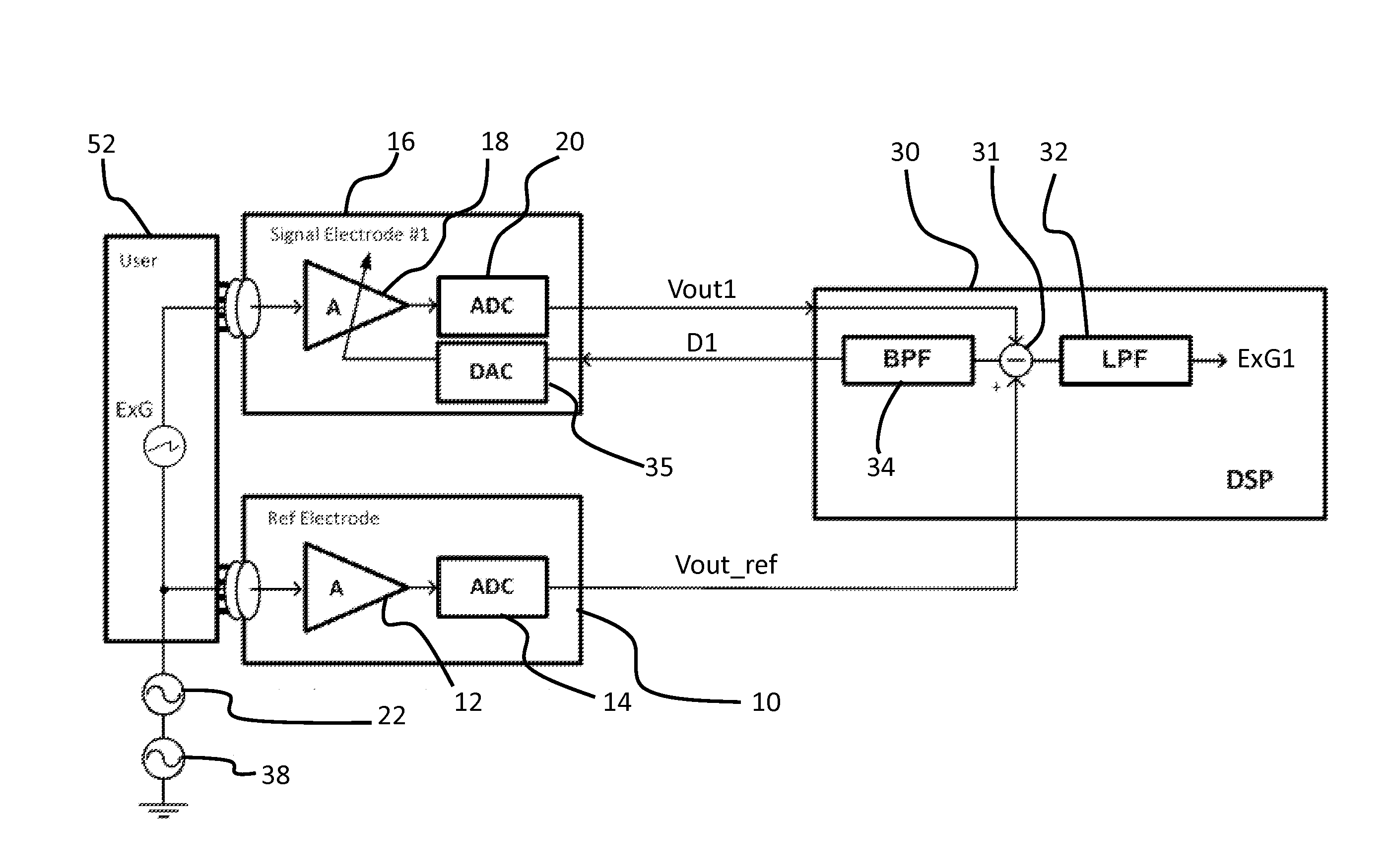
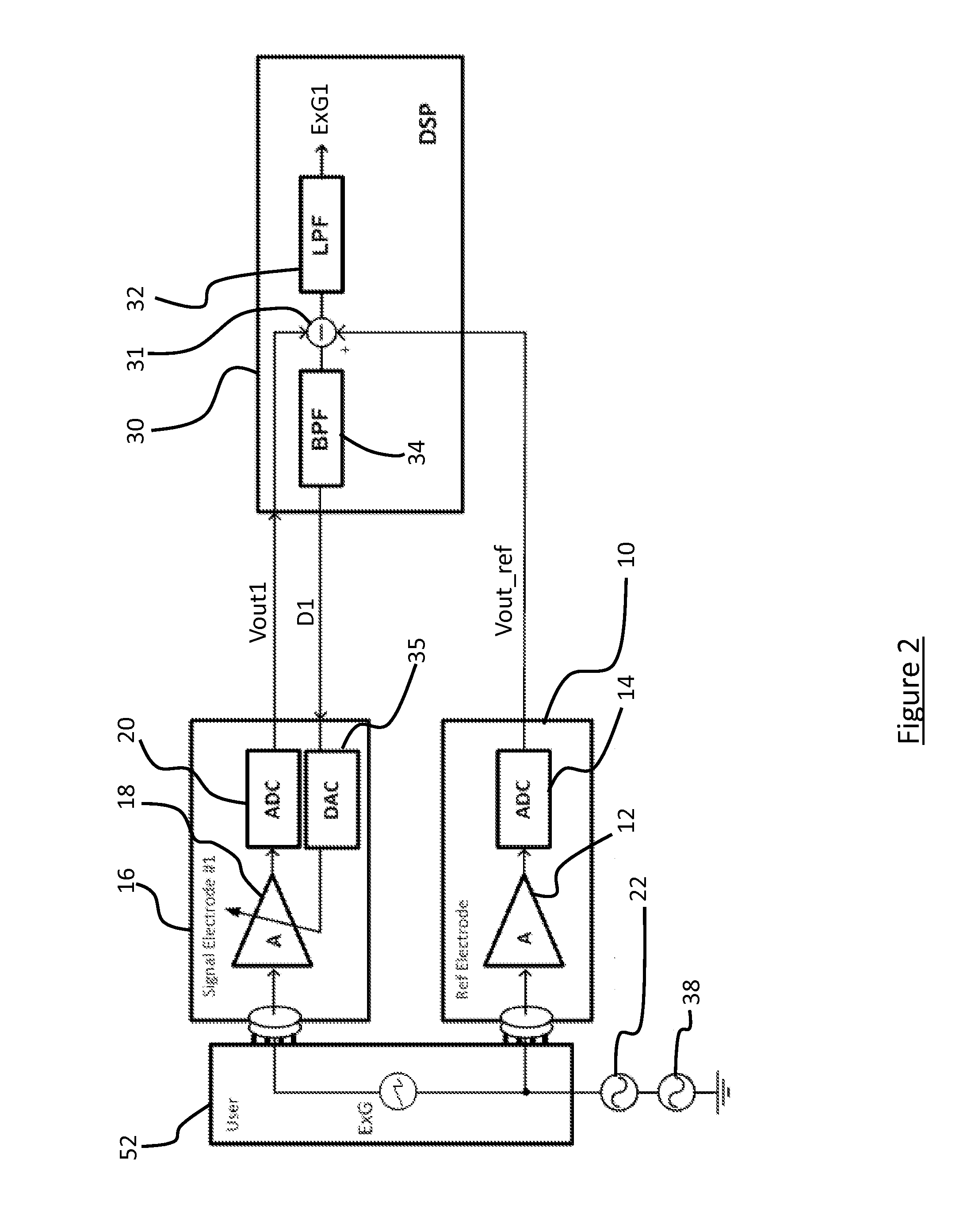
[0037]FIG. 2 shows a first example of signal acquisition system of the disclosure.

[0038]The same reference numbers are used as in FIG. 1 for the same or similar components. The ADC 20 of the signal active electrode 16 generates an output Vout1 and the ADC 14 of the reference active electrode 10 generates an output Vout_ref.

[0039]The referenc...


PUM


Abstract

A biopotential signal acquisition system, comprising: a first active electrode including an integrated pre-amplifier and an analogue to digital converter; a second active electrode including an integrated pre-amplifier and an analogue to digital converter, wherein the second active electrode has variable gain; a test signal generator for generating a test signal at a test frequency and coupling the test signal to the first and / or second active electrodes; and a digital signal processor configured to: process the digital outputs of the first and second active electrodes to derive a gain control signal based on a difference between the first and second active electrode outputs at the test frequency, and apply the gain control signal to the second active electrode. The disclosure also relates to an electronic circuit or device and a biopotential signal acquisition method.

Description

CROSS-REFERENCE TO RELATED APPLICATION[0001]This application claims priority to European Patent Application No. 13173917.9 filed on Jun. 27, 2013, the contents of which are hereby incorporated by reference.FIELD OF THE DISCLOSURE[0002]This disclosure relates to the acquisition of biopotential signals, such as, for example, ECG (electrocardiography), EEG (electroencephalography) or EMG (electromyography) signals.BACKGROUND OF THE DISCLOSURE[0003]Biopotentials are usually recorded using electrodes attached to the body, such as wet (gel) electrodes, or dry electrodes. The electrodes are used to measure biopotentials, which typically have a magnitude in the range of about 1 μV to 10 mV.[0004]Active electrodes have been employed in biopotential acquisition systems, in which the electrodes are integrated with amplifiers for the suppression of interference picked up from cables. The active electrode based system is robust to cable motion artifacts and interferences, which makes it suitable...

Claims


Application Information

Patent Timeline
Patent Type & Authority Applications(United States)
IPC IPC(8): A61B5/0476A61B5/04A61B5/0428A61B5/00A61B5/0488A61B5/0402A61B5/0496A61B5/296A61B5/308
CPCA61B5/7207A61B5/0402A61B5/0476A61B5/04004A61B5/0496A61B5/0428A61B5/0488A61B5/0478H03F3/45533A61B5/0408A61B2562/0209A61B5/0492A61B5/30A61B5/25A61B5/291A61B5/296A61B5/318A61B5/369A61B5/389A61B5/398
Inventor XU, JIAWEIYAZICIOGLU, REFET FIRAT
Owner INTERUNIVERSITAIR MICRO ELECTRONICS CENT (IMEC VZW)
Why Eureka
Try Eureka