Circuit for discriminating between battery charging signals and RF telemetry signals received by a single coil in an implantable medical device

a single coil and telemetry technology, applied in the field of implantable medical devices, can solve the problems of reducing the power consumption of the device, reducing the flexibility and versatility of the target, and pns design being more complex and expensive. the effect of power consumption reduction

Active Publication Date: 2015-01-08
WILSON GREATBATCH LTD
View PDF2 Cites 28 Cited by
  • Summary
  • Abstract
  • Description
  • Claims
  • Application Information

AI Technical Summary

Benefits of technology

[0009]Another aspect of the present disclosure involves a medical device for providing an electrical stimulation therapy for a patient. The medical device includes a coil configured to receive both inductive charging signals and telemetry signals. The inductive charging signals are in a first frequency band. The telemetry signals are in a second frequency band that is substantially higher than the first frequency band. The medical device includes inductive charging circuitry configured to provide electrical power to the medical device via the inductive charging signals. The medical device includes telemetry circuitry configured to conduct telecommunications with external device via the telemetry signals. The medical device includes a first component that is electrically coupled between the coil and the inductive charging circuitry. The first component is configured to allow the inductive charging signals to pass through. The medical device includes a second component that is electrically coupled between the coil and the telemetry circuitry. The second component is configured to substantially block the inductive charging signals while allowing the telemetry signals to pass through.
[0010]Another aspect of the present disclosure involves a medical system for providing an electrical stimulation therapy for a patient. The medical system includes an electronic programmer configured to generate first telemetry signals that contain stimulation programming instructions for an implantable pulse generator (IPG) and second telemetry signals for waking up the IPG. The medical system includes the IPG configured to generate electrical pulses in response to the stimulation programming instructions. The IPG contains an antenna configured to receive the first telemetry signals, the second telemetry signals, and inductive charging signals. The inductive charging signals are in a first frequency band, the first telemetry signals are in a second frequency band that is substantially higher than the first frequency band, and the second telemetry signals are in a third frequency band that is substantially higher than the second frequency band. The IPG contains an inductive charging circuitry configured to provide electrical power to the medical device via the inductive charging signals. The IPG contains telemetry circuitry configured to conduct telecommunications with external device via the telemetry signals. The IPG contains a first circuit that is electrically coupled between the antenna and the inductive charging circuitry. The first circuit contains one or more electronic components that create a resonant frequency centered around the first frequency band. The IPG contains a second circuit that is electrically coupled between the antenna and the telemetry circuitry. The second circuit is configured to substantially reject the inductive charging signals and the second telemetry signals while allowing the first telemetry signals to pass through. The IPG contains a third circuit that is electrically coupled between the antenna and the telemetry circuitry and in parallel with the second circuit. The third circuit is configured to reject the inductive charging signals and the first telemetry signals while allowing the second telemetry signals to pass through.
[0011]Another aspect of the present disclosure involves a method of providing discrimination for a plurality of types of input signals received from a single antenna. The method includes receiving, via the single antenna, inductive charging signals and first telemetry signals. The inductive charging signals are in a first frequency band, the first telemetry signals are in a second frequency band that is substantially higher than the first frequency band. The method includes generating, via a first circuit coupled to the single antenna, a resonant frequency substantially near the first frequency band such that the first circuit allows the inductive charging signals to pass through while attenuating the first telemetry signals. The method includes rejecting, v

Problems solved by technology

Therefore, a typical paddle lead for a conventional PNS device or for spinal cord stimulation does not offer the flexibility and versatility needed to stimulate the target nerve fibers for peripheral nerve stimulation, as they are not configured to allow electrical stimulation energy to follow the tortuous peripheral nerve targets selectively.
As a result, PNS design is more complex and more expensive.
As yet another example, conventional PNS devices typically do not employ sophisticated power maximi

Method used


Image

  • Circuit for discriminating between battery charging signals and RF telemetry signals received by a single coil in an implantable medical device
  • Circuit for discriminating between battery charging signals and RF telemetry signals received by a single coil in an implantable medical device
  • Circuit for discriminating between battery charging signals and RF telemetry signals received by a single coil in an implantable medical device

Examples


Embodiment Construction

[0032]It is to be understood that the following disclosure provides many different embodiments, or examples, for implementing different features of the invention. Specific examples of components and arrangements are described below to simplify the present disclosure. These are, of course, merely examples and are not intended to be limiting. Various features may be arbitrarily drawn to different scales for simplicity and clarity.

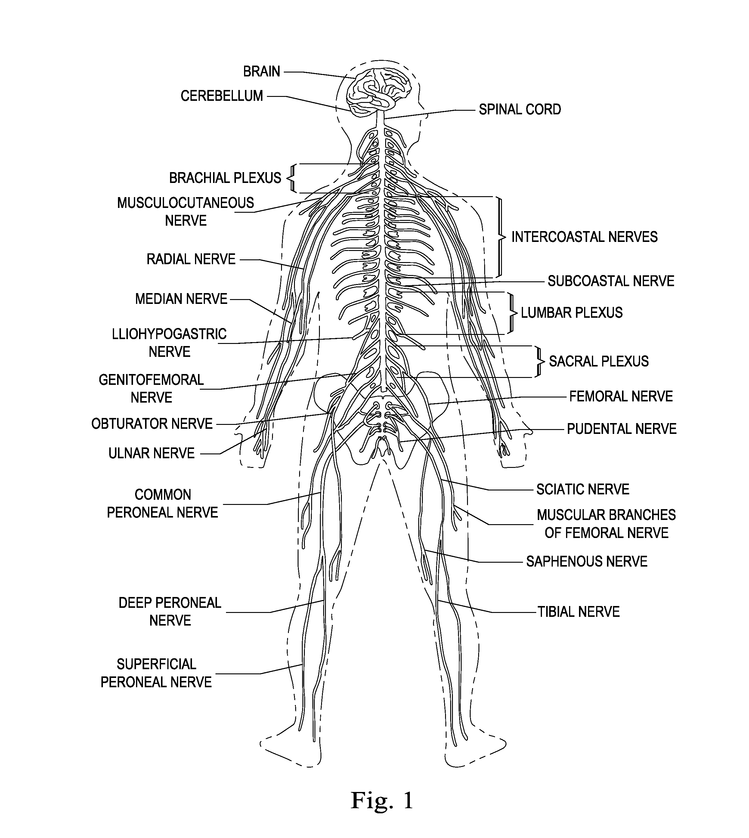
[0033]The human nervous system includes a complex network of neurological structures that extend throughout the body. As shown in FIG. 1, the brain interconnects with the spinal cord which branches into the brachial plexus near the shoulders and the lumbar plexus and sacral plexus in the lower back. The limb peripheral nerves of the arms extend distally from the brachial plexus down each arm. Similarly, the limb peripheral nerves of the legs extend distally from the lumbar plexus and sacral plexus. A number of the larger limb peripheral nerves are identified ...


PUM


Abstract

A medical device for providing a stimulation therapy includes a coil configured to receive both inductive charging and telemetry signals. The inductive charging signals are in a first frequency band. The telemetry signals are in a second frequency band higher than the first frequency band. The medical device includes inductive charging circuitry configured to provide electrical power to the medical device via the inductive charging signals. The medical device includes telemetry circuitry configured to conduct telecommunications with external device via the telemetry signals. The medical device includes a first component electrically coupled between the coil and the inductive charging circuitry. The first component is configured to allow the inductive charging signals to pass through. The medical device includes a second component electrically coupled between the coil and the telemetry circuitry. The second component is configured to substantially block the inductive charging signals while allowing the telemetry signals to pass through.

Description

PRIORITY DATA[0001]The present application is a utility application of provisional U.S. Patent Application No. 61 / 841,965, filed on Jul. 2, 2014, entitled “Stimulation Apparatuses, Devices, Systems, and Methods,” the disclosure of which is hereby incorporated by reference in its entirety.FIELD[0002]Various embodiments described herein relate to the field of implantable medical devices, and methods of communicating therewith.BACKGROUND[0003]As medical device technologies continue to evolve, neurostimulator devices have gained much popularity in the medical field. Neurostimulator devices are typically battery-powered devices that are designed to deliver electrical stimulation to a patient. Through proper electrical stimulation, the neurostimulator devices can provide pain relief for patients. In effect, the electrical signals sent by the neurostimulator devices “mask” or modify the pain signals before the pain signals reach the patient's brain. As a result, the patient may feel only a...

Claims


Application Information

Patent Timeline
IPC IPC(8): A61N1/372
CPCA61N1/37252A61N1/37223A61B8/0841A61N1/0551A61B5/064A61N1/05A61N1/0553A61N1/36017A61N1/36021A61N1/36071A61N1/36125A61N1/36139A61N1/36146A61N1/36153A61N1/37235A61N1/3752A61N1/3787
Inventor CHEN, JOEY
Owner WILSON GREATBATCH LTD
Why Eureka
Try Eureka