
Structural panels, cladding assemblies and components

a technology of cladding and components, applied in the direction of walls, covering/linings, building components, etc., can solve the problems of droplets that run down the back of the cladding sheet, dry structure of the building, disassembly and assembly, etc., to achieve the effect of improving structural and insulative properties, easy and convenient assembly

Active Publication Date: 2015-01-15
VIREO
View PDF14 Cites 10 Cited by
  • Summary
  • Abstract
  • Description
  • Claims
  • Application Information

AI Technical Summary

Benefits of technology

The patent describes a cladding system that can be easily assembled to provide an exterior cladding for building requirements. The cladding system includes multiple components with different profiles and functions, such as panels and end-caps, that can interface with each other. The system also has an exterior cladding layer with a moisture impervious outer surface and an integrated raceway gutter system to evacuate any water and moisture that penetrates the seams or is diverted from anywhere. Ribs may also be provided on the interior side of the exterior cladding layer and a moisture impervious and / or heat reflective layer may be added between the insulation layer and the capillary break. The end-caps designed to divert and carry away any liquid that penetrates the façade. Overall, the cladding system has a technical effect of preventing moisture and water penetration into buildings, while also providing an easily assembled and effective exterior cladding solution.

Problems solved by technology

When successfully designed and installed, the structural frame of the building remains dry, as water never reaches it or the thermal insulation.
This, however, typically forms droplets that run down the back of the cladding sheets and are dissipated through evaporation and drainage.

Method used


Image

  • Structural panels, cladding assemblies and components
  • Structural panels, cladding assemblies and components
  • Structural panels, cladding assemblies and components

Examples


Embodiment Construction

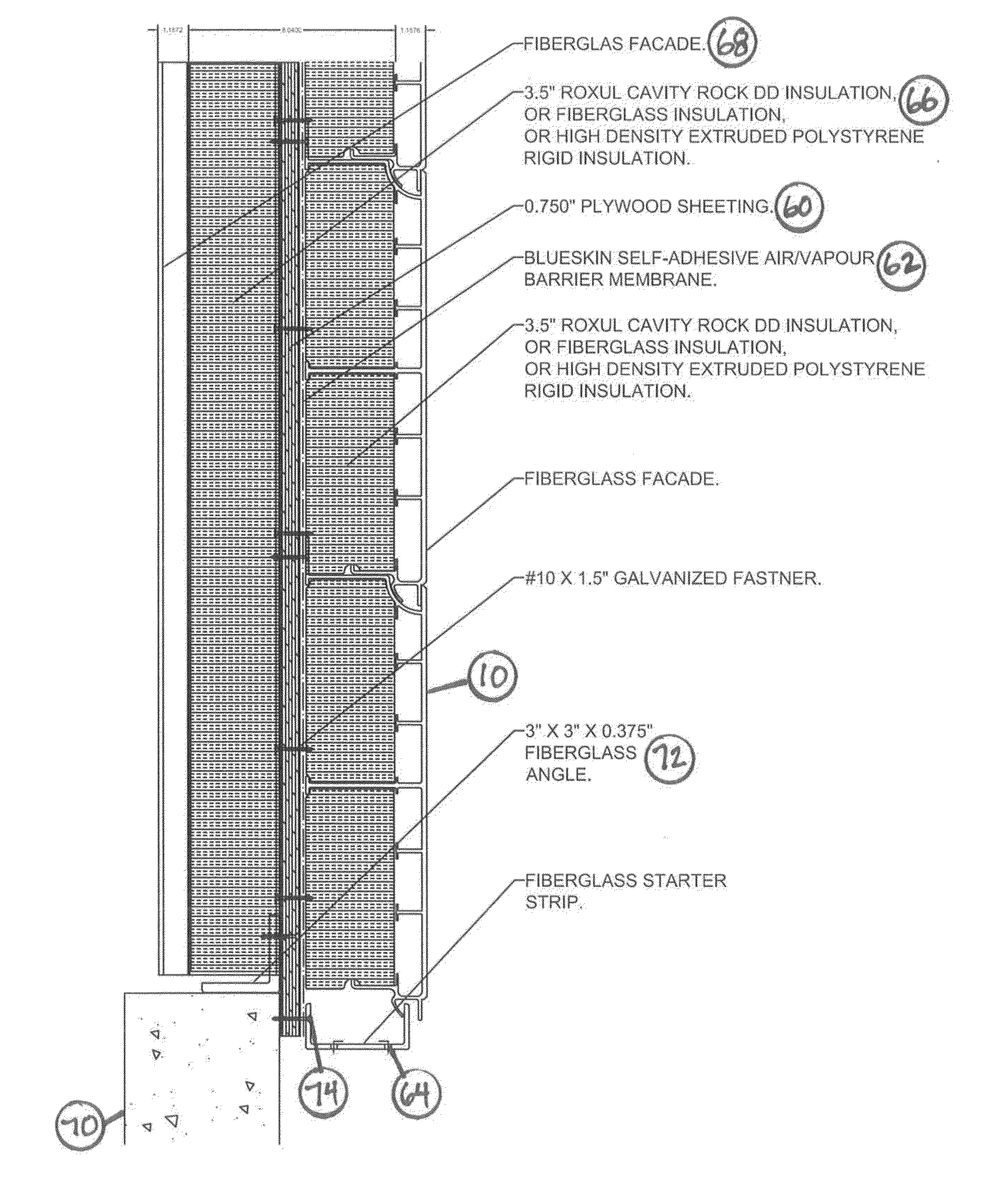
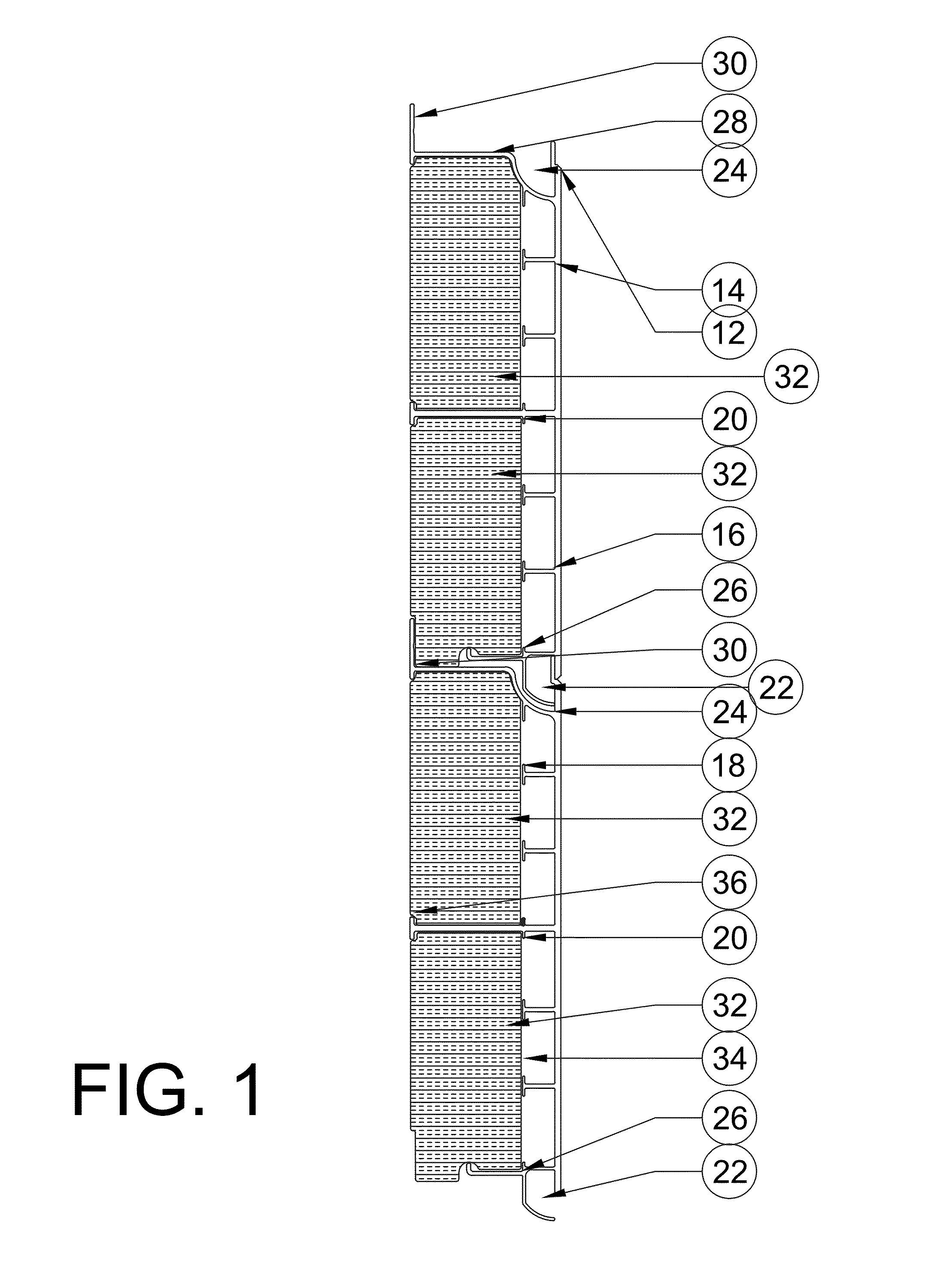
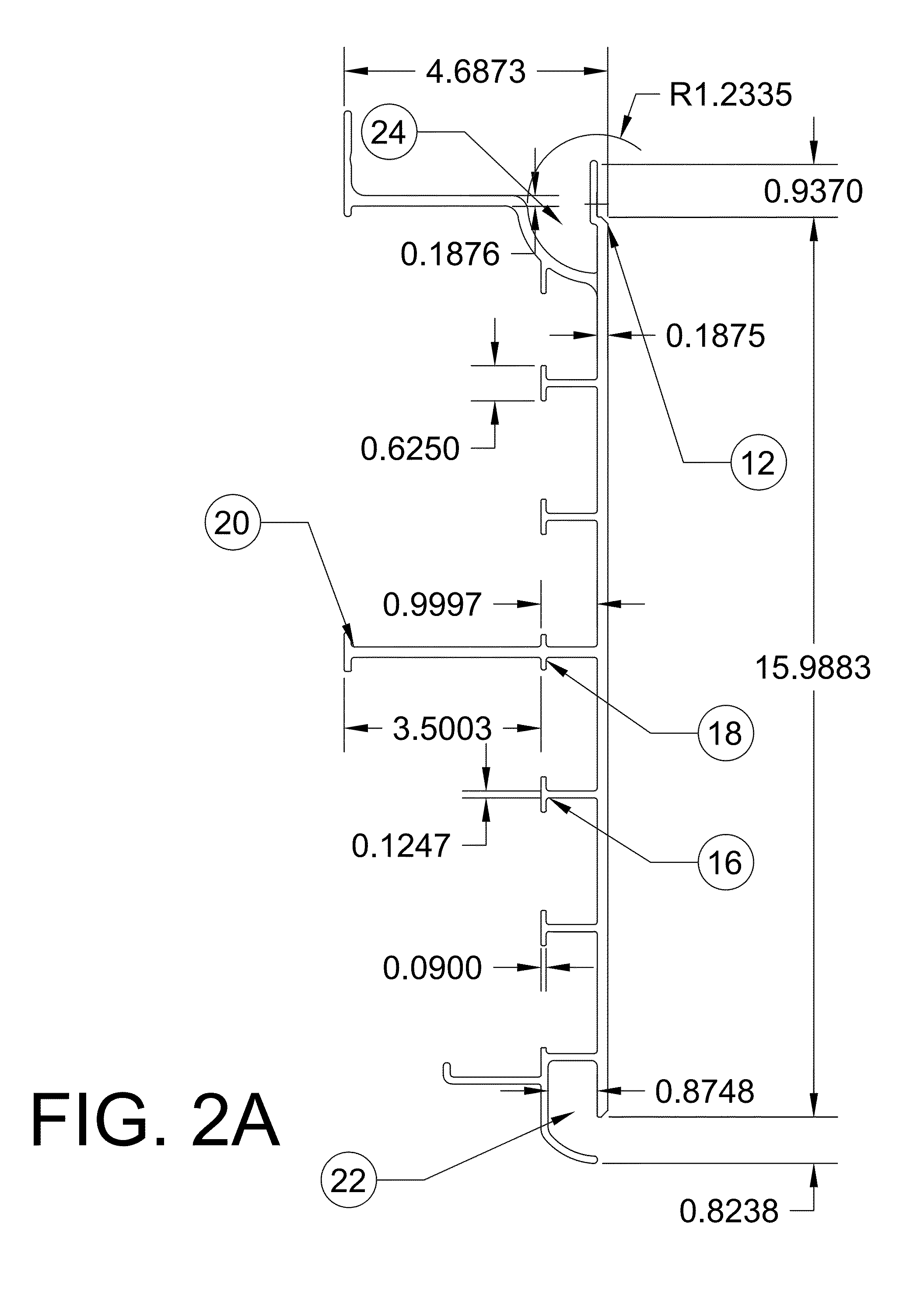
[0013]FIG. 1 illustrates one embodiment of two exterior cladding panels of the present invention interlocked with one another and FIG. 2A shows an integral structural façade panel as illustrated in FIG. 1 with the insulation component removed. While FIG. 2A shows dimensional information for one embodiment of an integral structural façade component, it will be appreciated that these dimensions may be varied considerably without departing from the invention. The exterior cladding panels 10, in this embodiment, are composed of an exterior cladding layer 12 having an external surface 14 and a plurality of backwardly extending ribs 16. In the illustrated embodiment, ribs 16 are integral with the exterior façade and terminate in stops 18. Each exterior cladding panel 10 may (optionally) have one or more extended ribs 20 extending backwardly further than other ribs. Extending ribs 20 may provide support and facilitate positioning of insulation components, and may perform other functions as...


PUM

PropertyMeasurementUnit
Distanceaaaaaaaaaa
Heataaaaaaaaaa
Reflectionaaaaaaaaaa

Abstract

Structural panels, components and assemblies are described. The structural panel system comprises one or more panels having interlocking profile features providing convenient assembly of multiple panels to provide pre-assembled panels or structures, or components that are easily shipped and assembled at a site to satisfy a variety of building requirements, transport requirements, structural panel requirements, and the like. An integrated raceway gutter system may be provided for evacuation of moisture in conjunction with end-caps having a coordinating structure. Insulation components may be positioned at an interior side of panels and may be separated from the capillary break by a moisture impervious and / or heat reflective layer. Cladding panels may be pre-assembled, along with additional structural building components, to provide pre-assembled structural insulative (and non-insulative) panels. Additional system components, including end caps, a sill, a head, a façade, a jamb and accessory brackets, are also described.

Description

TECHNICAL FIELD OF THE INVENTION[0001]The present invention relates to structural panels, cladding assemblies and components for use in construction, transport, and a variety of other applications. In some aspects, the present invention relates to modular panels having an internal cavity that may be filled with an insulative material to provide thermally and acoustically insulated structural panels for use in a variety of applications.BACKGROUND OF THE INVENTION[0002]Rainscreen cladding generally refers to a construction façade rainscreen system which consists of the subframe assembly in combination with different finishes, such as cladding panels, brick, ceramic tiles, reconstituted stone boards, ceramic granite based on a natural stone, high-pressure laminates, composite aluminum panels, metal panels (aluminum, zinc, steel), fiber-cement board, or durable exterior woods. An outer skin of rear-ventilated cladding is typically mounted to a new or existing building subframe. Rainscre...

Claims


Application Information

Patent Timeline
IPC IPC(8): E04B1/70E04C2/52E04F13/08E04F13/09E04C2/22E04C2/38
CPCE04C2/521E04F13/09E04C2/22E04B1/7038E04C2/38E04F13/0889E04C2/296E04C2/388E04C2/523E04B2/46
Inventor SAWATZKY, JOHNSAWATZKY, HERMANHENRY, MIKE
Owner VIREO
Learn More